COMPONENT MAINTENANCE MANUAL
AVIATION RECORDERS
Model FA5000
Initial Issue Page 706
Sep. 30/11
Assembly
23–70–40
Use or disclosure of information on this sheet is subject to
the restrictions on the cover page of this document.
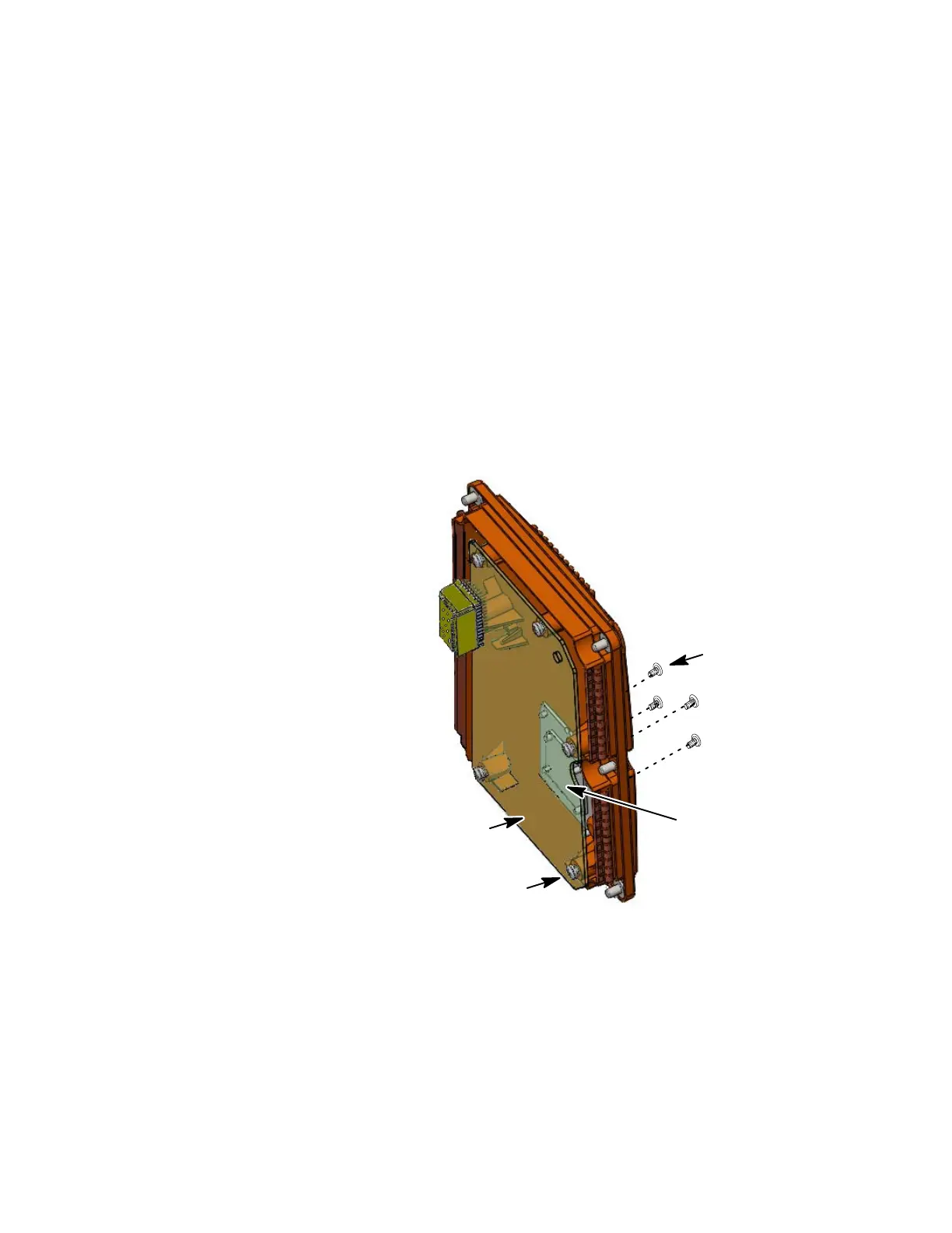
(1) Place the AI PWA (1−30) into position on the Rear Cover (1−10).
(2) Install the six screws (1−35) used to secure the AI PWA (1−30) to the rear cov-
er (1−10). Tighten screws to a torque value of 9−10 in./lbs.
(3) install the four screws (1−40) used to secure the Rear Connector J1 to the back
of the rear cover (1−10). Tighten screws to a torque value of 5-6 in./lbs.
(4) Install the rear cover as described in Paragraph E, Rear Cover Installation.
(1−30)
(1−35)
(Qty. 6)
(Qty. 4)
(1−40)
Rear Connector
J−1
Some parts are removed
for clarity purposes
NOTE:
Torque (9−10 in/lbs)
Torque (5−6
in/lbs)
Figure 703.
Aircraft Interface PWA Installation Diagram
The document reference is online, please check the correspondence between the online documentation and the printed version.
 Loading...