COMPONENT MAINTENANCE MANUAL
AVIATION RECORDERS
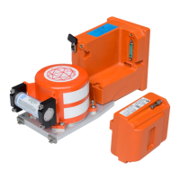
Model FA5000
Initial Issue Page 702
Sep. 30/11
Assembly
23–70–40
Use or disclosure of information on this sheet is subject to
the restrictions on the cover page of this document.
3. ASSEMBLY INSTRUCTIONS
CAUTION:THE FA5000 CIRCUIT BOARDS ARE SUSCEPTIBLE TO ELECTRO–STATIC
DESTRUCTION (ESD). PRIOR TO HANDLING PWAs, ENSURE PROPER PER-
SONNEL GROUNDING TECHNIQUES ARE USED. INSURE THAT CARDS ARE
PLACED INTO STATIC SHIELDING CONDUCTIVE BAGS WHEN HANDLING OR
STORING.
A. General Assembly Techniques
The Model FA5000 circuit board components are mounted using Surface Mount
Technology (SMT) and also incorporate extensive software programming to function-
ally configure the logic circuits. Thus, Level-3 repair of these circuit boards requires
specialized factory equipment, diagnostic software, training, and techniques; there-
fore, such boards are not field-repairable while the unit is under warranty. Conse-
quently, in accordance with the accepted Level-2 repair philosophy for the FA5000
CVDR, a known defective circuit board assembly shall be returned to the factory for
repair or replacement.
NOTE
: Numbers shown in parentheses in the following text are the
Illustrated Parts List (IPL) figure number followed by the IPL
item number for a particular part; e.g., (1-115) for IPL Figure 1,
Item 115. For items listed in the parts list but not illustrated, the
item number is preceded by a “-”.
The Assembly procedures begin with the Video Card PWA (P/N: 5001−6133−11
only) installation then continue with the Main Processor PWA, Aircraft Interface PWA
installation, CSMU installation, and Underwater Acoustic Beacon installation.
B. Video Card PWA Installation( for P/N: 5001−6133−11 only)
(See 701 or IPL Figure 1, Item 175)
VIDEO CARD INSTALLATION PROCEDURE
(1) Align the Video Card PWA (1−175) connectors with J−3 and J−4 connectors on
the MP PWA (1−50).
(2) Install the three stand−offs (1−185) and eight screws (1−180) to secure the
Video Card PWA (1−175) to MP PWA (1−50). Tighten screw to a torque value
of 2−3 in./lbs.
The document reference is online, please check the correspondence between the online documentation and the printed version.
 Loading...