COMPONENT MAINTENANCE MANUAL
AVIATION RECORDERS
Model FA5000
Initial Issue Page 703
Sep. 30/11
Assembly
23–70–40
Use or disclosure of information on this sheet is subject to
the restrictions on the cover page of this document.
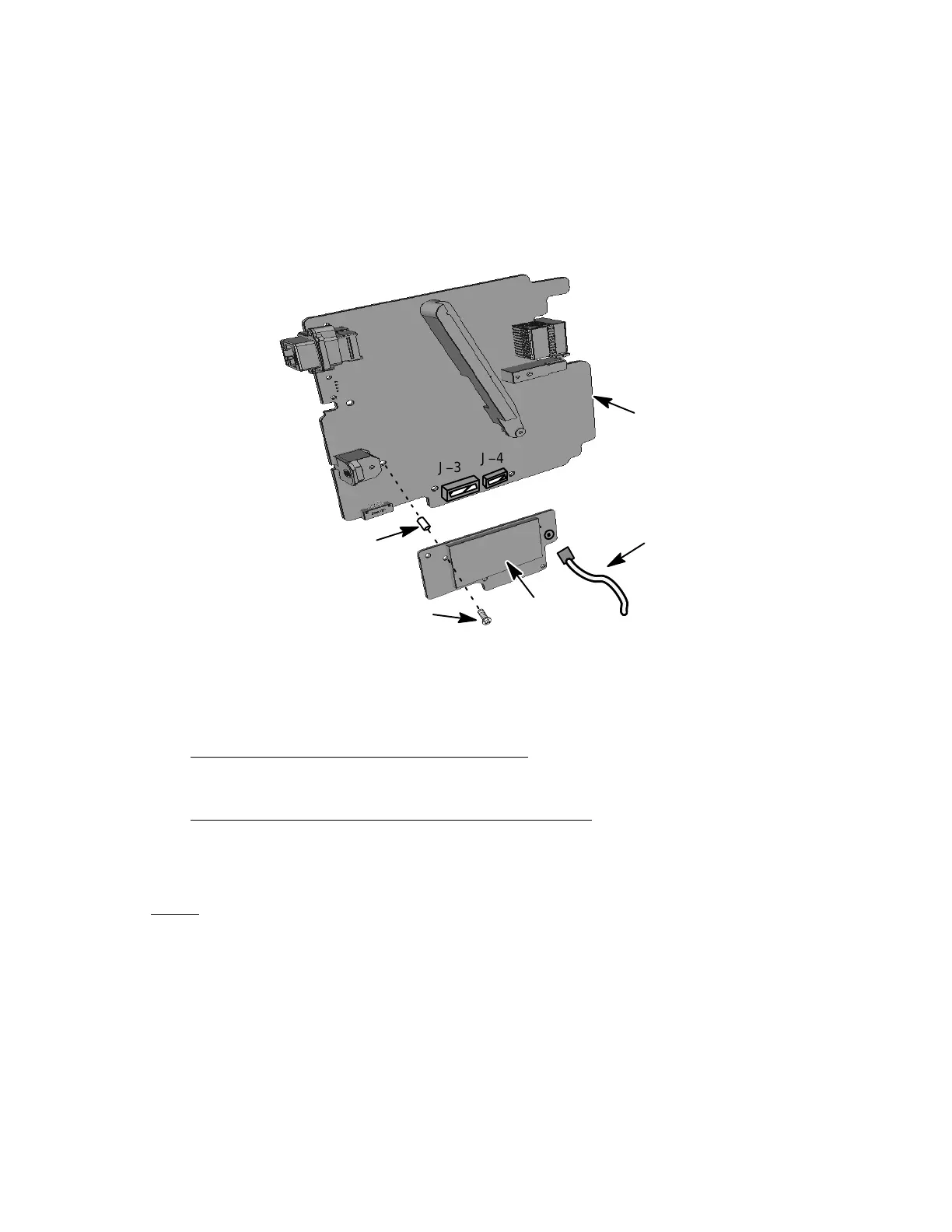
(3) Connect the Video Cable (1−190) connector to J−1 on the the Video Card PWA
(1−175).
(4) Install the MP PWA (1−50) as described in Paragraph C, Main Processor PWA
Installation.
(1−185)
(1−180)
Some parts are removed
for clarity purposes
NOTE:
(QTY 3)
(QTY 8)
J−3
J−4
(1−175)
(1−50)
(1−190)
Torque
(2−3
in/lbs)
J−1
Figure 701. Video Card Installation Diagram
C. Main Processor (MP) PWA Installation
(See Figure 702 or IPL Figure 1, Item 50)
MAIN PROCESSOR INSTALLATION PROCEDURE
(1) Slide straight in and forward on the MP PWA (1−50) using the guides in the
Shielded Housing (1−5) to ensure no damage to the Ethernet connector.
NOTE
: Apply Loctite to all screw installations for the following proced-
ures:
(2) Install the lower one screw (1−55) used to secure the front end of the MP PWA
(1−50) to front part of the Shielded Housing (1−5). Tighten screw to a torque
value of 5-6 in./lbs.
(3) Install the one screw (1−55) used to secure the lower half Ethernet connector
J2 to the front part of the Shielded Housing (1−5). Tighten screw to a torque
value of 2−3 in./lbs.
The document reference is online, please check the correspondence between the online documentation and the printed version.