COMPONENT MAINTENANCE MANUAL
AVIATION RECORDERS
Model FA5000
Initial Issue Page 705
Sep. 30/11
Assembly
23–70–40
Use or disclosure of information on this sheet is subject to
the restrictions on the cover page of this document.
DETAIL “A”
(1−65)
(1−70)
(1−75)
(1−60)
(1−120)
(1−55)
(1−50)
(1−85)
(QTY 2)
(QTY 2)
SEE DETAIL “A”
P−5
Connector
(1−110)
(1−115)
(QTY 2)
(1−135)
(1−100)
J2
Connector
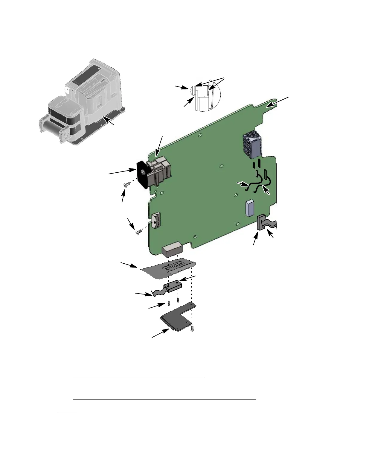
Some parts are removed
for clarity purposes
NOTE:
(1−5)
(REF,)
(QTY 2)
J−7
J−6
RED
BLACK
(1−140)
Torque (5−6
in/lbs)
Torque
(5−6 in/lbs)
Torque
(2−3
in/lbs)
Torque2−3
in/lbs)
Figure 702. Main Processor (MP) Installation Diagram
D. Aircraft Interface PWA (AI) Installation
(See Figure 703 or IPL Figure 1, Item 30)
AIRCRAFT INTERFACE PWA INSTALLATION PROCEDURE
NOTE: Apply Loctite to all screw installations for the following proced-
ures:
The document reference is online, please check the correspondence between the online documentation and the printed version.
 Loading...