COMPONENT MAINTENANCE MANUAL
AVIATION RECORDERS
Model FA5000
Initital Issue Page 7
Sep. 30/11
Description and Operation
23–70−40
Use or disclosure of information on this sheet is subject to
the restrictions on the cover page of this document.
4. HARDWARE / SOFTWARE INTERFACE DATA
A. Cockpit Area Microphone Internal PreAmplifier Attenuation
Eight different Cockpit Area Microphone audio pre-amplifier input signal attenuation levels are
available. The attenuation level is realized by using J1-Pin48, J1-Pin49, and J1-Pin50 as
OPEN/GND address inputs to decode one of the eight possible attenuation levels. The default
address is OPEN, voltage HIGH on each of the three pins and provides the audio input signal
reference level. The GND, voltage LOW state results by connecting any of the address inputs
to J1-54 (INT_PRE_AMP_ATTEN_COMMON)presents the possible combinations of J1-Pin48,
J1-Pin49, and J1-Pin50 with the corresponding attenuation level of the Cockpit Area Micro-
phone audio signal.
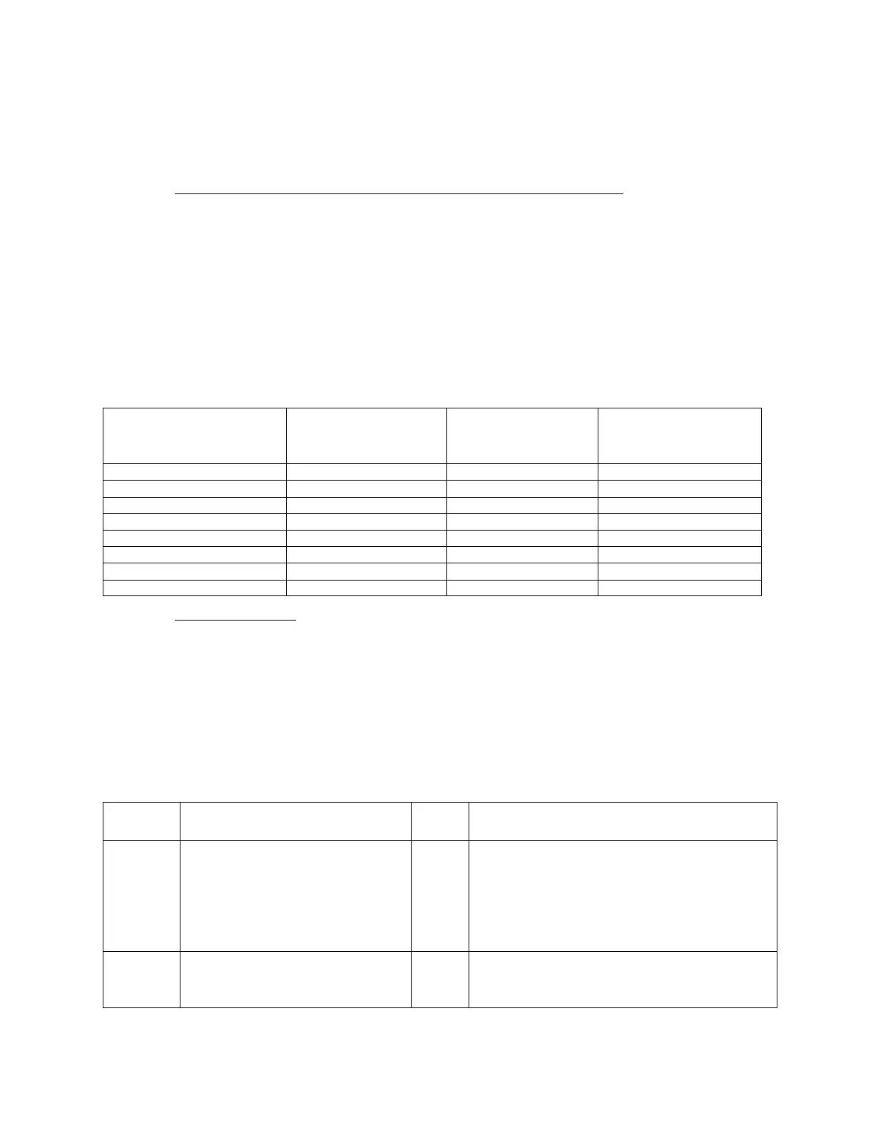
Table 1. Cockpit Area Microphone PreAmplifier Input Attenuation Decode
J1Pin50,
n24dB_CAM_INPUT
J1Pin49,
n12dB_CAM_IN
PUT
J1Pin48,
n6dB_CAM_IN
PUT
ATTENUATION,
±1dB
(GdB)
GND GND GND 42
GND GND OPEN 36
GND OPEN GND 30
GND OPEN OPEN 24
OPEN GND GND 18
OPEN GND OPEN 12
OPEN OPEN GND 6
OPEN OPEN OPEN GdB0
B. Signal Directory
Aircraft Interface PWA to Aircraft, J1
Signal Directory for the FA5000 Cockpit Voice and Data Recorder MIL-C-38999 Interface
defines the FA5000 CVDR equipment pin−out utilizing a MS27508E16F35P,
MIL-C-38999, Series II connector with PCB tails (Amphenol 10-565998-198N). The air-
craft side mating connector is an MS27473E16F35S (or equivalent).
Table 2. Processor Board PWA to Aircraft Interface PWA, P1
Pin
Number
Signal Names MAIN
I/O
Comment
A1 PreAmplifier_Power O +18.5 volts DC, diode isolated, and
30mA current limited power to AI. This
output is in parallel with the Area_Micro
phone_Power. Referenced to the Signal
Ground. Not used in the FA5000, cir
cuitry not populated on AI PWA.
H1 Analog_Audio_Input1 I Differential analog input. Channel 1 au
dio input, line high. Referenced to the
Signal Ground.
The document reference is online, please check the correspondence between the online documentation and the printed version.
 Loading...