3B-26 - FUEL SYSTEM 90-830234R3 DECEMBER 1997
Acceleration Pump Circuit Operation
- Four Cylinder Engines
ACCELERATOR PUMP - Receives pressurized fuel
from T-fitting in fuel line between #1 and #2 carbure-
tors. Pump is actuated by throttle cam. Pumps to two
check valve/injector nozzles in #3 and #4 cylinder
boost passages.
FUEL FILTER - 74 micron filter. Prevents debris from
plugging check valve/injector nozzles.
CHECK VALVE/INJECTOR NOZZLE - 2 assem-
blies, one each for #3 and #4 cylinders. Fuel passes
from check valve thru 0.026 inch orifice (injector
nozzle) and into respective cylinder boost passage.
FLOW RESTRICTOR - Helps equalize pressure
within the accelerator pump circuit while allowing air
or any vapor which has formed to pass through and
be vented at the carburetors.
FUEL CONNECTOR - Spring loaded shut off valve
which connects boat fuel tank with outboard fuel sys-
tem.
IMPORTANT: The distance between the accelera-
tor pump and the throttle cam determines the
amount of fuel the accelerator pump will dis-
charge. If accelerator pump is moved or re-
placed, refer to SECTION 2C for correct position-
ing of accelerator pump.
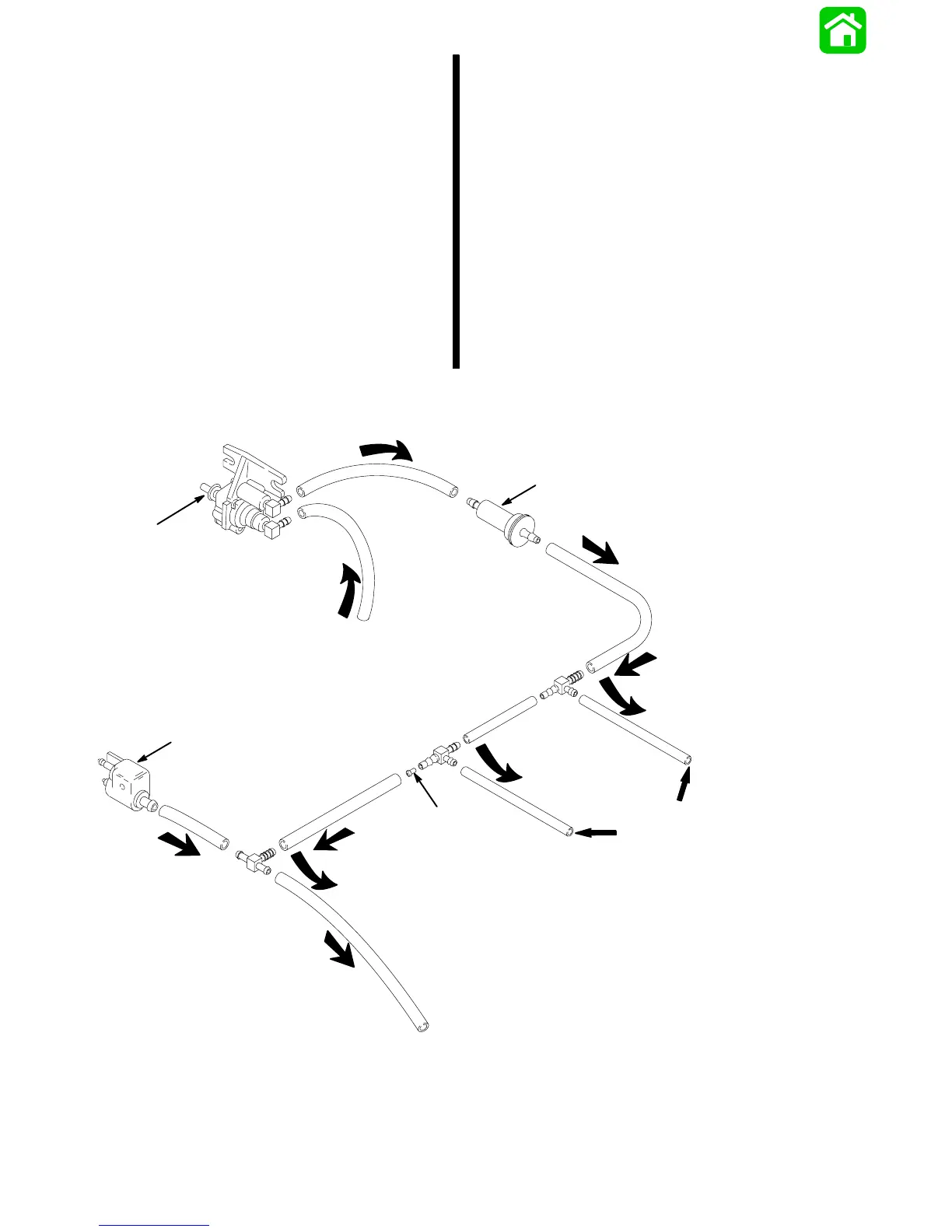
ACCELERATOR PUMP FUEL FLOW CIRCUIT
From T-Fitting between
#2 and #3 Carburetors
To #3 and #4 Cylinder Check
Valve/Injector Nozzles
To Fuel Pump
a
b
c
d
a - Accelerator Pump
b - Fuel Filter
c - Flow Restrictor
d - Fuel Connector
 Loading...