90-830234R3 DECEMBER 1997 LOWER UNIT - 6A-9
b
c
a
53922
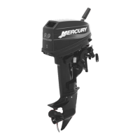
a - Oil Level Screw
b - Fill/Drain Screw
c - Vent Screw
2. Inspect gear lubricant for metal particles (lubri-
cant will have a “metal flake” appearance). Pres-
ence of fine metal particles (resembling powder)
on the drain plug bar magnet indicates normal
wear. The presence of metal chips on the drain
plug bar magnet indicates the need for gear
housing disassembly and component inspection.
3. Note color of gear lubricant. White or cream color
MAY indicate presence of water in lubricant. Gear
lubricant which has been drained from a gear
case recently in operation will have a yellowish
color due to lubricant agitation/aeration. Gear
lube which is mixed with assembly lubricant
(Special Lube 101 or 2-4-C w/Teflon will also be
creamy white in color. This is normal and should
not be confused with the presence of water. If wa-
ter is suspected to be present in gearcase, a
pressure check of gearcase should be made
(with no lubricant in gearcase). Gearcase should
hold 10 to 12 psi (68 – 82 kPa) of pressure for 5
minutes without leaking down. Pouring a portion
of the gear lubricant into a glass jar and allowing
the lubricant to settle will allow any water in the
lube to separate and settle to the bottom of the jar.
4. Presence of water in gear lubricant indicates the
need for disassembly and inspection of oil seals,
seal surfaces, O-rings, water pump gaskets as
well as gear housing components for damage. If
gearcase is rebuilt, gearcase should be pressure
checked before filling with lubricant.
Water Pump
1. If water tube seal stayed on water tube (inside of
drive shaft housing) when gear housing was re-
moved, pull water tube seal from water tube.
2. Replace water tube seal, if damaged.
3. Remove 4 bolts, washers, and isolators.
4. Remove cover.
c
b
b
a
19212
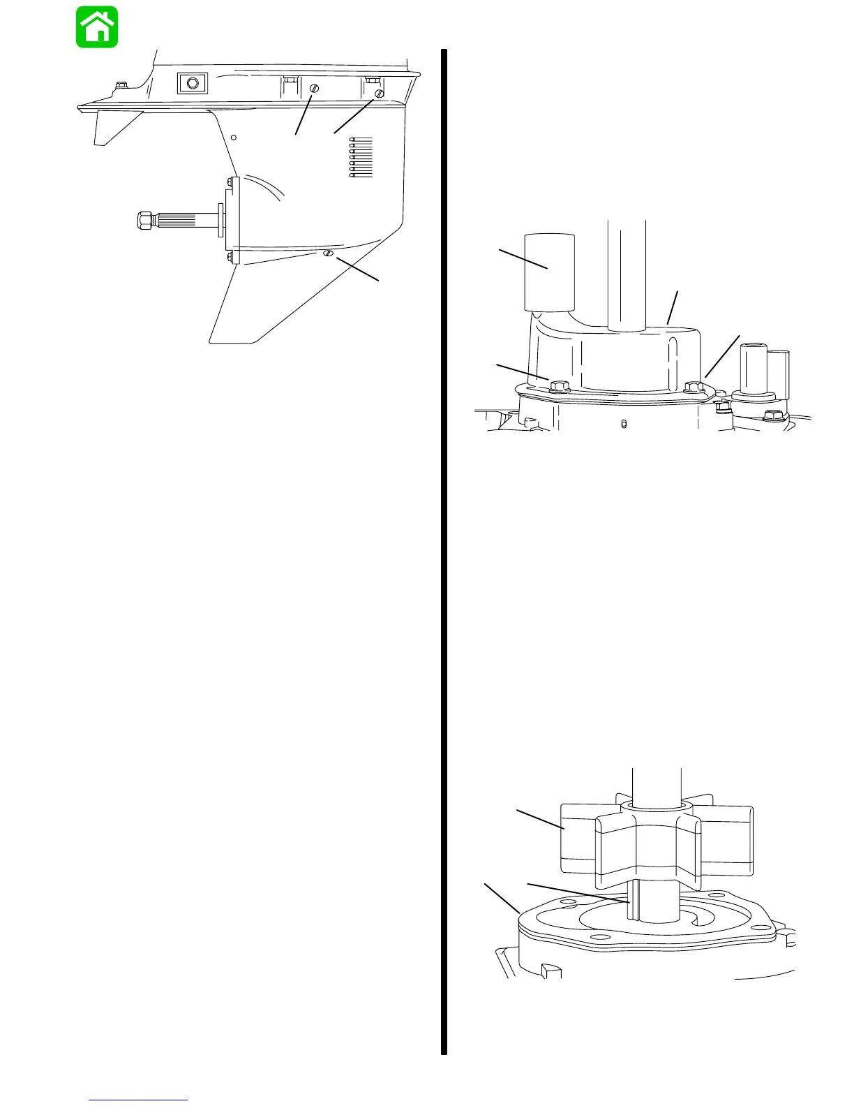
a - Water Tube Seal
b - Bolts (4 each)
c - Cover
IMPORTANT: The circular groove formed by the
impeller sealing bead should be disregarded
when inspecting cover (Step 5) and plate (Step 9),
as the depth of the groove will not affect water
pump output.
5. Replace cover if thickness of steel at the dis-
charge slots is 0.060 in. (1.52mm) or less, or if
groove(s) (other than impeller sealing bead
groove) in cover roof are more than 0.030 in.
(0.76mm) deep.
6. Lift impeller, drive key, and gasket from drive
shaft.
c
b
a
19220
a - Impeller
b - Drive Key
c - Gasket
 Loading...