Structure and Assembly/Disassembly 7-27
PCB shielding cover.
2. Remove the self-tapping screw PT3X10 (2 pcs) for fixing the keyboard first, then take
out the keyboard.
Fig 7-9 Disassemble the monitor keyboard
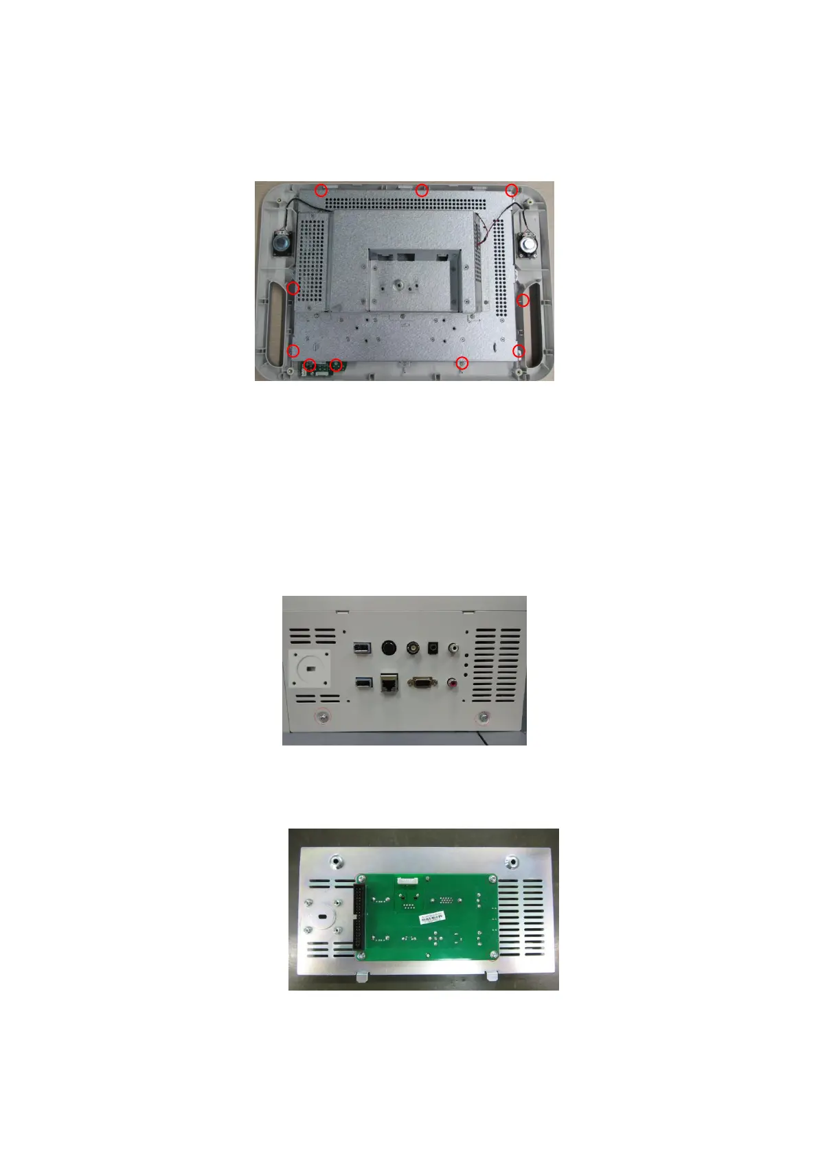
7.4.2 IO Rear Board
Tool: Cross-headed screwdriver. Please refer to Chapter 7.3.1 Tools Required for tools’
specifications.
1. Remove the M4X8 screws (2 pcs) which are used to secure the IO module, and then
the IO module can be removed.
Fig 7-10 Disassemble the IO Board Assembly
2. Remove the fixing screws M3X8 (4 pcs) of IO Rear board from the IO module, then
IO Rear board can be removed.
Fig 7-11 Disassembly of the IO Rear board
3. If ECG module is configured, you need to disassemble the ECG module.
 Loading...


