4-6 Hardware Principle
IO interface board supports REMOTE signal, which is obtained by Multifunction
FPGA on the main board.
USB signal, Ethernet signal and VGA signal on the IO interface board are
obtained by CPU module output.
Transfer the audio output signal of the main board to the speakers on both sides
of the monitor.
4.2.5 IO Rear board
IO interface board
Port connecting IO interface
board and IO rear board
Port connecting IO rear
board and IO interface
board
Cable connection
IO backplane
USB port
VGA
S-VIDEO
VIDEO
Network
interface
REMOTE
Cable connection
Network port
Network port
USB port
Power
indicators
AUDIO
Figure 4-6 Principle Diagram of IO Rear board
IO Rear board contains the following ports:
2 USB ports, used for peripherals connection such as printer.
Network interface.
VIDEO port, S-VIDEO port and Remote port.
External VGA port.
Power indicators ports for 12V, 5V and 3.3V powers.
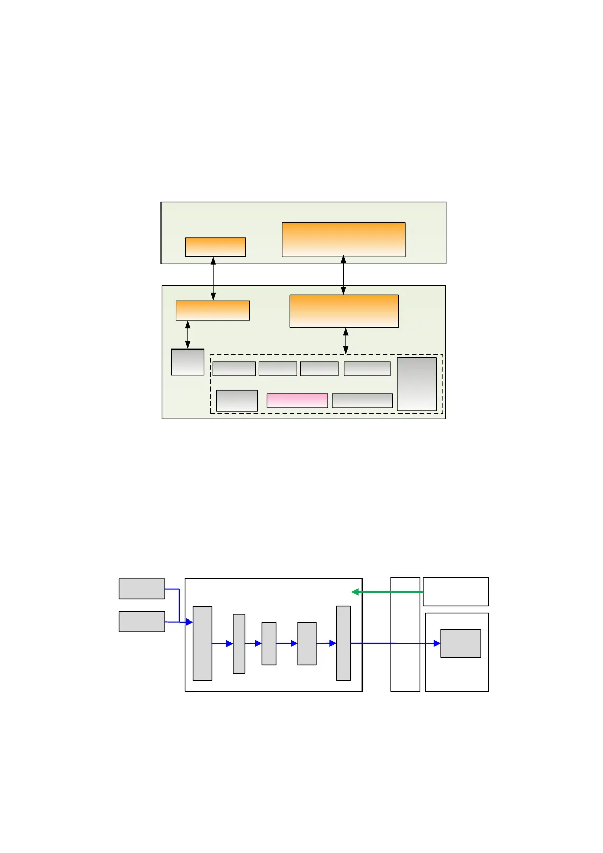
4.2.6 ECG Board
IO
board
Main board
ECG lead
DC IN
Socket Interface
Amplification
Filtering
Sampling
R wave Detection
DSP
FPGA
ECG board
DC-DC
board
Pwr
Serial
Port
Fig 4-7 Principle Diagram of ECG Board
ECG board is aimed at ECG signal detection as well as ECG wave display as
reference for ultrasound image.
 Loading...


