Hardware Principle 4-7
The ECG signal, 2D image and color flow image are simultaneously displayed
on the system.
After amplification, filtering and sampling, the ECG signal will be sent to DSP
board and R-wave detection is conducted at the same time.
The detected ECG triggering signal will be sent to the DSP FPGA on the main
board through serial port.
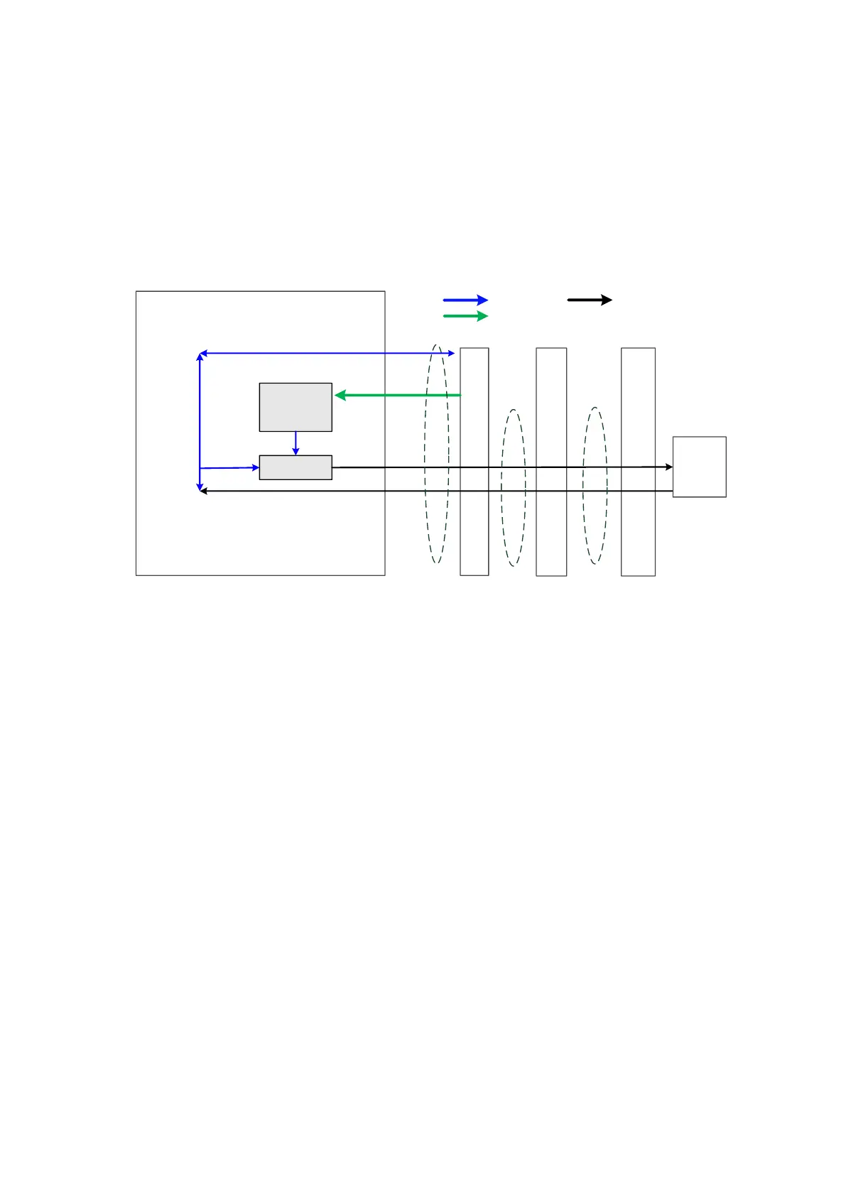
4.2.7 4D Driving Board
Main board
Probe Connected Assembly
Probe board
4D Drive Board
Communication signal
Power
amplication
Voltage
control
Motor driving signal
4D probe Hall return signal
12V
Socket connection
4D
probe
Socket connection
Communication &
Control
Power supply
Ultrasonic signal
Socket connection
Figure 4-8 Principle Diagram of 4D Drive Board
Amplifies 4D drive signal power and output signal matching the power
requirement to drive the transducer to the desired position;
Provide 4D Hall signal returning channel.
 Loading...


