Hardware Principle 4-5
Multifunction FPGA on the back-end of the main board is to implement the
REMOTE port on the IO interface board.
The CPU module implements interfaces including USB, Ethernet and VGA on
the IO interface board
System monitor circuit connects Multifunction FPGA though smbus.
Multifunction FPGA communicates with ARM by serial port to control
transmission high-voltage, and also implements ARM update by serial port.
FPGA on the power supply module implements the system power on/off by the
switch signal.
Standby indicator, AC present indicator and working status indicator on the
control panel are output by FPGA.
The control panel implements communication with CPU module by USB.
The CPU module output the audio signals to the IO interface board..
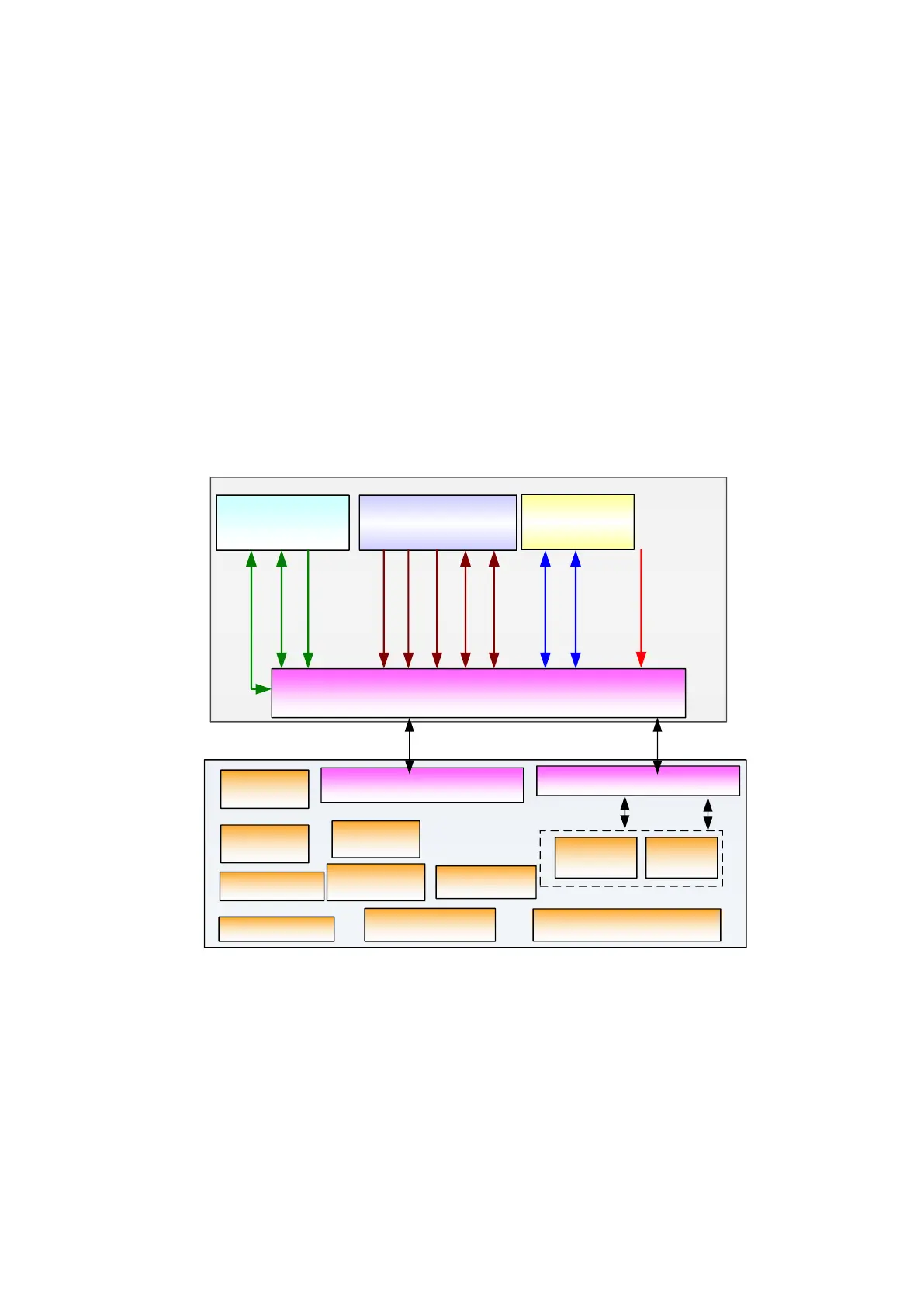
4.2.4 IO Interface Board
CPU module
Multifunction module
System monitor
circuit
Port connecting main board and IO interface board
VIDEO
S-VIDEO
REMOTE
Main
board
DVI
USB 4/5
ETHERNET
Status
indicator
BTB connection
IO Interface
board
Port connecting main board
port and IO interface board
VGA
Port connecting IO connecting
board and IO Rear board
Fan control
signal
Port connecting
DVI and I2C
Control Panel adapter port
Cable connection
Control panel
signal port
Control
panel
power port
Board
connection
Main unit fan port
I2C
Network port
Monitor power
port
DVD-RW
power port
+5V
+12V
+3.3V
Monitor audio
port
Main unit audio
and ECG port
HDD power
port
Figure 4-5 Principle Diagram of IO interface board
IO interface board connects to the main board via connectors in order to implement
the user interface function. Main functions include:
Transfer signals from main board to IO Rear board, control panel, monitor, ECG
board and etc.
Power the display module, DVD-RW, HDD, control panel, ECG board and etc.
Support connections of all signal ports on the IO Rear board.
IO interface board supports signals of Video and S-Video, the two channels of
which are obtained by Multifunction Module including Video Encoder and
Multifunction FPGA.
 Loading...


