1. GENERAL DESCRIPTION
1 − 3
1.1 System Configuration
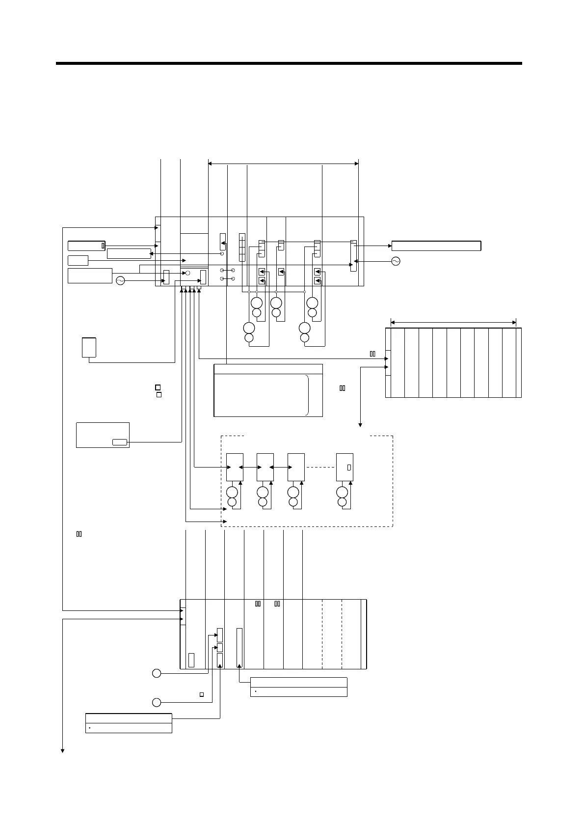
1.1.1 A273UHCPU System overall configuration
The following system configuration assumes use of the A273UHCPU.
A62P A273UH
CPU
A278
LX
A240
DY
A221
AM-20
A211
AM-20
A222AM-20 A230P
A270BATCBL
MR-J-BAT
Emergency
stop input
A6BAT
AC100/200V
Brake output
Battery module
Regenerative brake resistor
Three-phase power supply
200V
DBOUT
DBCOM
DB IN+
DB IN-
M
E
M
E
M
E
M
E
M
E
External input signals
Upper limit switch
Lower limit switch
Stop signal
Proximity dog
Speed-position change
PLC extension base connection cable(A370C B)
d1
M
E
d2
M
E
d3
M
E
d8
M
E
Servo amplifier, max. 8 axes/1 network
Termination
resistor
Max. 24 axes
MR-H-BN/MR-J2S-B/MR-J2-B
(Max. 32 axes including those of ADU)
PLC extension bases: up to 7 bases
Base number setting: base 1 to base 7
PLC extension base(A68B/A65B/A62B)
(AC B)
Power supply module
PLC slots
Max. 16 ADU axes
SSCNET1
SSCNET2
SSCNET3
Teaching unit
A31TU/A30TU(SV13 only)
Windows NT/98
Personal computer(IBM PC/AT)
SSCNET4
SSC I/F card/board
(A30CD-PCF/A30BD-PCF)
RS422
CPU base unit
(A278B/A275B)
Control power
supply module
CPU module
Servo external
signal
Dynamic brake
module
Servo power
supply module
Motion slots
AC motor drive
modules
BRAKE
A62P AI61 AX AY AH42
A42XY
Motion extension base unit
(A268B)
Control power supply
module
Pulse generator/
synchronous
encoder interface module
Interrupt input module
A273
EX
×
8
External interrupt input signals
16 points (I0 to I15)
P
Manual pulse
generator
(MR-HDP01)
E
Serial absolute
synchronous encoder
(MR-HENC)(SV22 only)
External input signal
TRA Tracking
Input module
Output module
I/O composite module
Motion extension base, up to 4 bases
(Base number setting: base 1 to base 4)
Motion extension base
connection cable
(AC B)
3
×
3
×
Communication cable
(A270CDCBL M/
A270BDCBL M)
3
×
Serial absolute
synchronous encoder
cable (MR-HSCBL M)
 Loading...