3. POSITIONING SIGNALS
3 − 1
3. POSITIONING SIGNALS
The internal signals of the servo system CPU and the external signals sent to the
servo system CPU are used as positioning signals.
(1) Internal signals
Of the devices available in the servo system CPU, the following four types are
used for the internal signals of the servo system CPU.
• Internal relay (M).............................. M2000 to M3839 (1840 points)
• Special relay (SP.M) ........................ M9073 to M9079 (7 points)
• Data register (D) .............................. D0 to D799 (800 points)
• Special register (SP.D) .................... D9180 to D9199 (20 points)
(2) External signals
The external signals input to the servo system CPU are the upper and lower
stroke end limit switch input signals, stop signals, proximity dog signal,
speed/position switching signal, and manual pulse generator input signals.
• Upper and lower stroke end ............
limit switch input signal
Signals that control the upper limit and
lower limit of the positioning range
• Stop signal ....................................... Stop signal for speed control
• Proximity dog signal......................... The ON/OFF signal from the proximity dog
• Speed/position switching signal....... Signal that switches control from speed to
position control
• Manual pulse generator input .......... Signal from the manual pulse generator
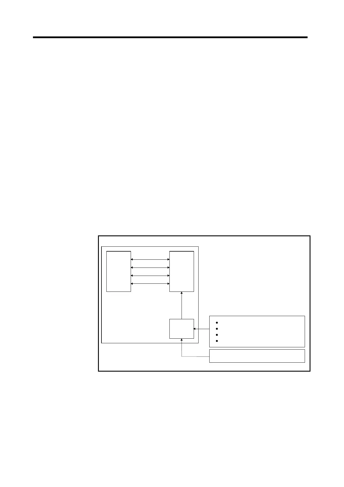
Servo System CPU System
SCPU PCPU
External
interface
SP.D, SP.M,
X
(Note-1)
Y
(Note-2)
D
(Note-3)
M
(Note-4)
Proximity dog signal
Speed/position switching signal
Upper limit/lower stroke end limit switch
Stop signal
Manual pulse generator
(Note-1): SP.D, SP.M and X are signals that notify
the SCPU of the PCPU control status.
(Note-2): Y are signals that notify the PCPU of
position control commands from the SCPU.
(Note-3): D are registers that notify the PCPU of
control commands from the SCPU and the
SCPU of control status information from
the PCPU.
(Note-4): M are flags that notify the PCPU of control
commands from the SCPU and the SCPU
of control status information from the PCPU.
Fig.3.1 Flow of positioning Signals
 Loading...