1. GENERAL DESCRIPTION
1 − 4
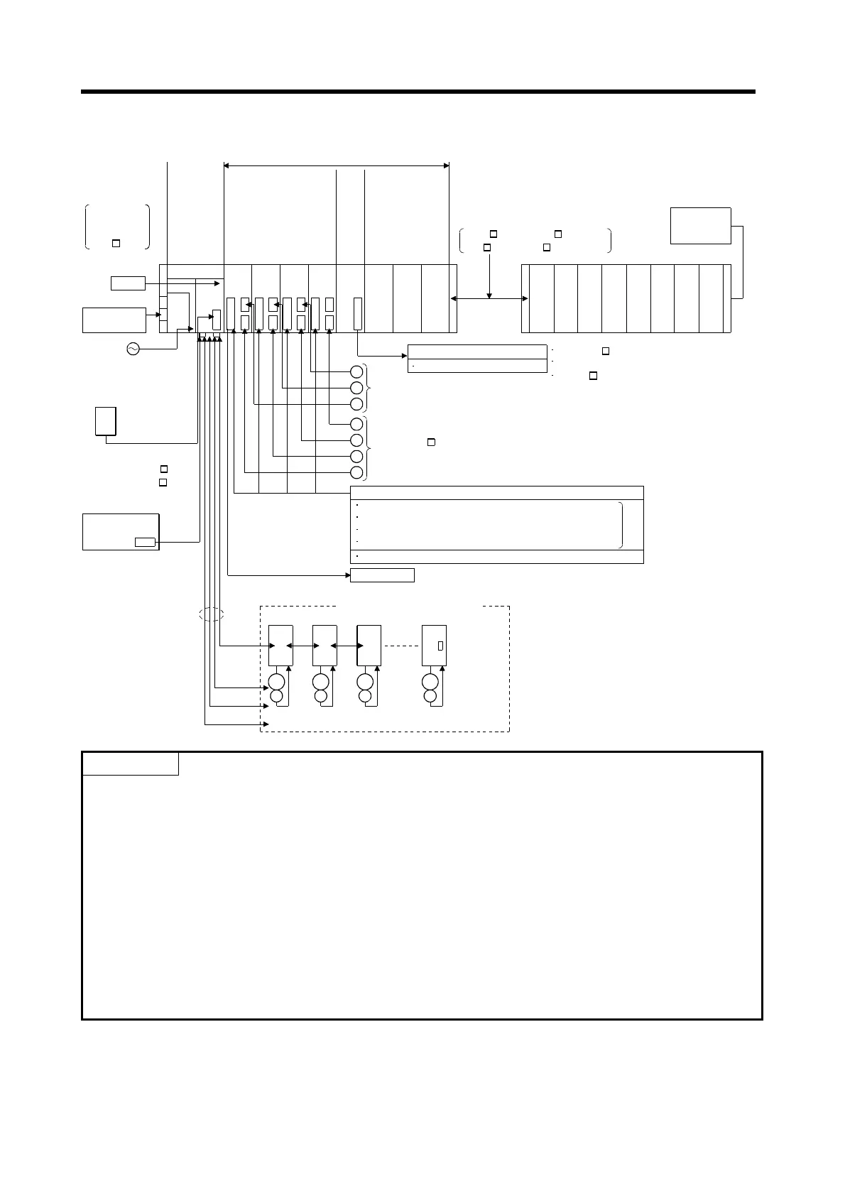
1.1.2 A173UHCPU(-S1) System overall configuration
Windows NT/98
d1
M
E
d2
M
E
d3
M
E
d8
M
E
Servo amplifier, max. 8 axes/1 network
Termination
resistor
MR-H-BN/MR-J2S-B/MR-J2-B
Servo amplifier, max. 32 axes
SSCNET1
A173UHCPU A172S
ENC
A1S
I61
Emergency
stop input
A6BAT
Teaching unit
A31TU-E/A30TU-E
(SV13 only)
Communication cable
(A270CDCBL M/
A270BDCBL M)
Personal computer
(IBM PC/AT)
SSCNET4
SSC I/F card/board
(A30CD-PCF/A30BD-PCF)
RS422
CPU module
Interrupt input module
External interrupt input signals
16 points (I0 to I15)
P
Manual pulse generator
(MR-HDP01)
E
External input signals
FLS Upper limit switch
RLS Lower limit switch
STOP Stop signal
DOG/CHANGE Proximity dog/speed-position change
TRA Tracking
Brake output
Motion network cable
Motion slots
Battery
AC100/200V
Power supply
module
PLC extension base
For A1S6 B: up to 1 base
For A168B (GOT compatible) : up to 1 base
For A6 B : up to 1 base
A172S
ENC
A172S
ENC
A172S
ENC
Pulse generator/
synchronous encoder
interface module
P
P
E
E
E
SSCNET3
SSCNET4
Max. 24 axes
SSCNET2
Extension cable
A1SC B: For A1S6 B, A168B
A1S NB: For A6 B
CPU base unit
A178B-S3
/A178B-S2
/A178B-S1
/A17 B
GOT
(Note)
(Note): The A173UHCPU may be used with 4 channels
of SSCNET.
When using the SSC I/F card/board
(A30CD-PCF/A30BD-PCF), connect it to
SSCNET4 and connect the servo amplifiers to
SSCNET1 to 3.
In this case, up to 24 axes of servo amplifiers
can be connected.
×
3
4
×
8
×
1
×
(Note)
Serial absolute
synchronous encoder cable
(MR-HSCBL M)
Serial absolute
synchronous encoder
(MR-HENC)
POINTS
(1) Use the A168B when using the bus-connection type GOT.
(2) Using the A31TU teaching unit provided with deadman switch requires the exclusively used
A31TUCBL03M connection cable between the CPU module and A31TU connector. The A31TU will
not operate at all if it is connected directly with the RS422 connector of the CPU, without using the
exclusively used cable.
Also, after disconnecting the A31TU, fit the A31SHORTCON short connector designed for
A31TUCBL.
(3) The motion slots also accept PLC A1S I/O modules.
(4) The motion slots accept one A1SI61 interrupt input module.
This module is designed for only event/NMI input to the motion CPU and is irrelevant to PLC
interrupt programs.
(5) The motion slots accept up to 256 I/O points.
(6) The I/O numbers of the I/O modules loaded in the motion slots should be later than the I/O numbers
used with the PLC slots.
 Loading...