CNUSR1
3mm
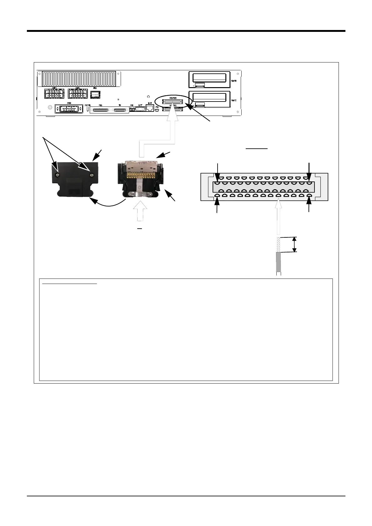
Connection procedure
Solder the user wiring connector that accompanies the product to the corresponding pin, and connect it to the
CNUSR1 connector at the back of the controller. For the connection cable, please use AWG #30 to 24 (0.05 to
0.2mm
2
).
1) Loosen the 2 fixing screws on the user wiring connector that accompanies the product, and remove the con
-
nector cover.
2) Peel the insulation of the connecting cable to 3mm, and solder it the appropriate connector pin number.
3) After the necessary cable has been soldered, re-fix the connector cover sing the same fixing screws and
make sure it is fastened securely.
4) Connect the connector to the corresponding connector (CNUSR1) on the controller. With pin number 1 facing
to the upper right, insert firmly until you hear the connector’s latch click in to place.
This concludes the connection procedure.
Cover fixing screw (Two places)
25
1
50
26
Connector cover
A
Plug
Remove the connector cover
Connector for
user wiring
View A
Pin number of plug
Soldering
Connecting cable
(AWG #30 ~ #24(0.05mm
2
to 0.2mm
2
))
* The controller is an example.
 Loading...