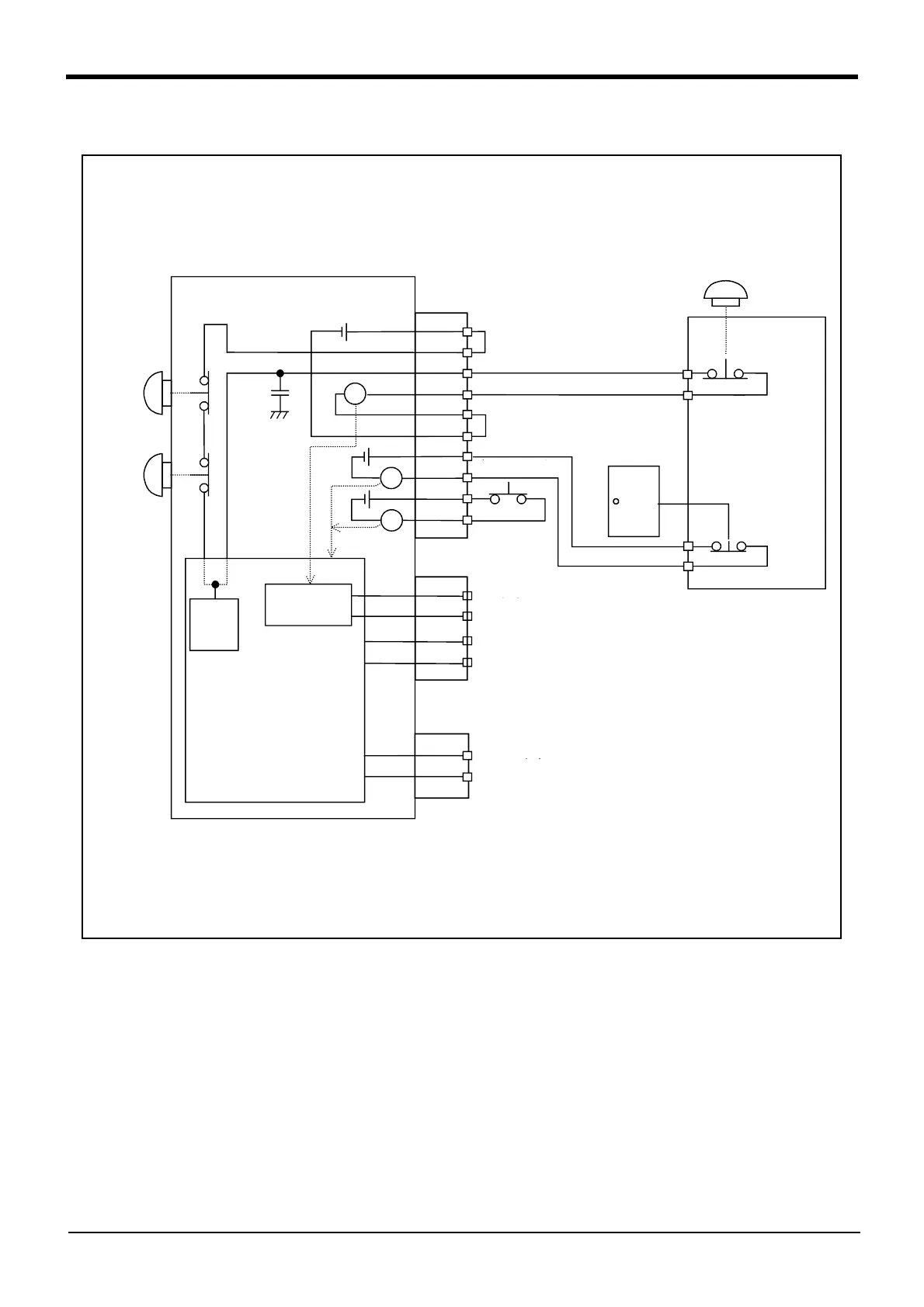
<Wiring example 1>: Connect the emergency stop switch of peripheral equipment to the controller.
The power supply for emergency stop input uses the power supply in the controller.
<Operation of the emergency stop>
If the emergency stop switch of peripheral equipment is pushed, the robot will also be in the emergency
stop state.
*1)Each of the connectors, EMG1 and
EMG2, are assigned with the same
pin number, creating two systems
for each terminal. It is absolutely
necessary to connect the two
systems.
*2)The T/B emergency stop button
connected with the controller.
*3)Emergency stop input relay.
*4)Refer to the Standard specification
manual or Special specification
manualfor the enabling device.
*1)
*1)
*3)
*5)The emergency stop input detection relay is used the controller’s internal safety relay control. If the emergency
stop input detection relay is switched OFF, emergency stop is detected and the safety relay is also switched OFF.
*6)
The emergency stop button of the robot controller. (Only specification with the operation panel.)
*5)
*1)
Controller
OP Emergency
stop button
TB Emergency
stop button
*2)
*6)
Power supply in the
robot controller 24V
Short circuit
(Short-circuited)
Short circuit
(Short-circuited)
Door switch input
Safety
fence door
Enabling
device
*4)
Mode output
Emergency stop output
Error output
Internal emergency stop
circuit
Safety relay
Emergency stop switch
(2- contact type)
Peripheral
equipment
Input
detection
circuit
 Loading...