Contrôleur
α
2
AL2-GSM-CAB 8
FRE-38
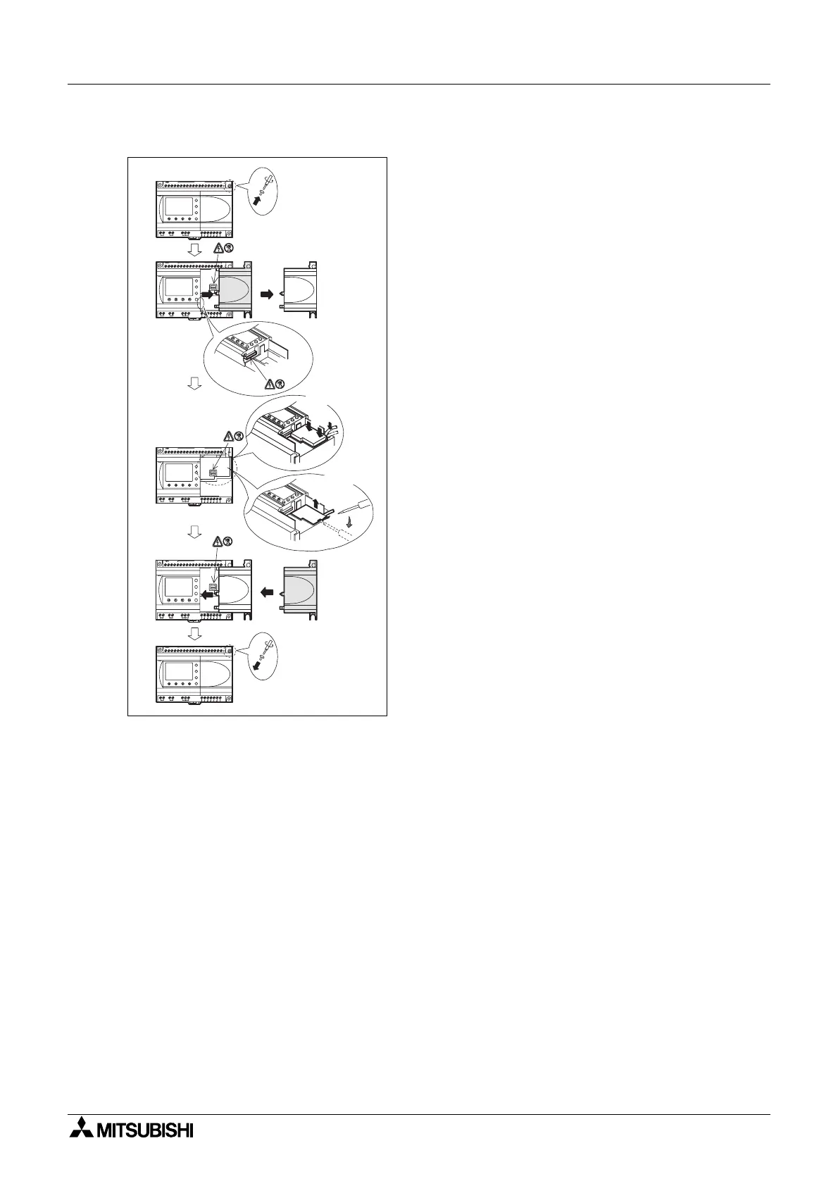
Figure 8.4: Installation
1) Dévissez la vis ‘A’etconservez-la.
2) Retirezavecprécaution le couvercle du port
d'extension
α
2 monté en usine ou le couvercle
du module spécial.
3) Installez le AL2-GSM-CAB dansson
emplacement,placer soigneusement le câble
dans le canal situé sur le côté de connexion de
l'entrée.
4) Fixez le couvercle
α
2oulemodule spécialen
faisant attention qu'aucune interférence avec le
AL2-GSM-CAB n'intervienne.
5) Remettez lavis‘A’enplaceetvissez-conservez-
lalaavec un couple de serrage compris entre 0,4
Nm.
OUT1
OK
-
+
ESC
OUT3
9
RELAY
OUTPUT
65
OUT
8
OUT2 OUT4
7
DC INPUT
151413121110987654321(B )(A )
+-
24V D C
POW ER
AL2-24MR-D
A
AL2-24MR-D
POW ER
24V D C
-+
(A)(B)123456789101112131415
DC INPUT
7
OUT4OUT2
8
OUT
56
OUTPUT
RELAY
9
OUT3
ESC
+
-
OK
OUT1
OUT1
OK
-
+
ESC
OUT3
9
RELAY
OUTPUT
65
OUT
8
OUT2 OUT4
7
DC INPUT
151413121110987654321(B )(A )
+-
24V D C
POW ER
AL2-24MR-D
A
1)
2)
3)
4)
5)
In s ta lle z
Retirez
AL2-24M R-D
POW ER
24V D C
-+
(A)(B)123456789101112131415
DC INPUT
7
OUT4OUT2
8
OUT
5
OUTPUT
RELAY
9
OUT3
ESC
+
-
OK
OUT1
AL2-24M R-D
POW ER
24V D C
-+
(A) (B) 1 2 3 4 5 6 7 8 9 10 11 12 13 14 15
D C IN P U T
7
OUT4OUT2
8
OUT
5
OUTPUT
RELAY
9
OUT3
ESC
+
-
OK
OUT1
6

 Loading...


