α
2 Simple Application Controllers
AL2-GSM-CAB 8
ENG-41
ENG
8.3.3 Modem Setting
1) Setting of personal computer side
Install the file for the setting of the attachment in the modem.
2) Setting of
α
2seriesside
The modem on the
α
2 series side is set by the ModemInit command of the main unit.
a) About the modem command (AT command)
Use the AT command to initialize the modem. Confirm details of the AT command in the
manual of the modem to be used. AT commands have been prepared for select modems
in the table 8.4 (normal modem) and 8.5 (GSM modem) below.
Further information on the method to initialize a modem can be found in the
α
2
Programming Manual.
When modems not listed in the table above are used, set the AT command to meet the
following requirements.
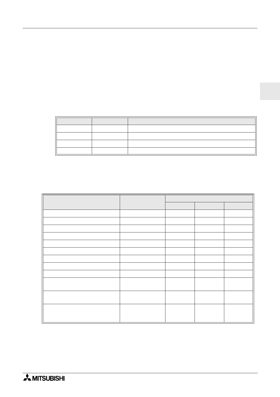
Table 8.3: Tested Modems
Maker name Model name Modem command (AT command)
3com SP560V-P ATE0Q1&B1&D0H0&I0&R1&S0S0=2S15=8&W
OMRON ME3314 ATE0S0=2Q1&D0S15=8&R1&H0&W
AIWA PV-AF3360 ATE0S0=2Q1&D0&M5\Q0\J0&W
Siemens M20T ATE0S0=2&S0;+IFC=0,0;+CMEE=1;+IPR=9600&W
Table 8.4: AT Command for Modem (Normal Modem)
Setting Item Set content
Example Setting
SP560V-P ME3314 PV-AF3360
Setting of command echo None E0 E0 E0
Call frequency of auto-answering Twice S0=2S0=2S0=2
Displayed result code None Q1 Q1 Q1
DTR control Always on &D0 &D0 &D0
DSR control Always on &S0
Communicate mode V.42bis mode S15=8S15=8 &M5
Speed of terminal fixed dimension Fixed &B1 \J0
Terminal flow control scheme None -&R1 \Q0
Flow control of transmission data None &H0 &H0 -
Flow control of received data
(software)
None &I0
Flow control of received data
(RTS control)
None &R1
Writing in nonvolatile memory
Writeinthe
nonvolatile
memory.
&W &W &W

 Loading...


