Technische Daten 2
α
2
-
Steuerung
GER-10
2.3 Ausgänge
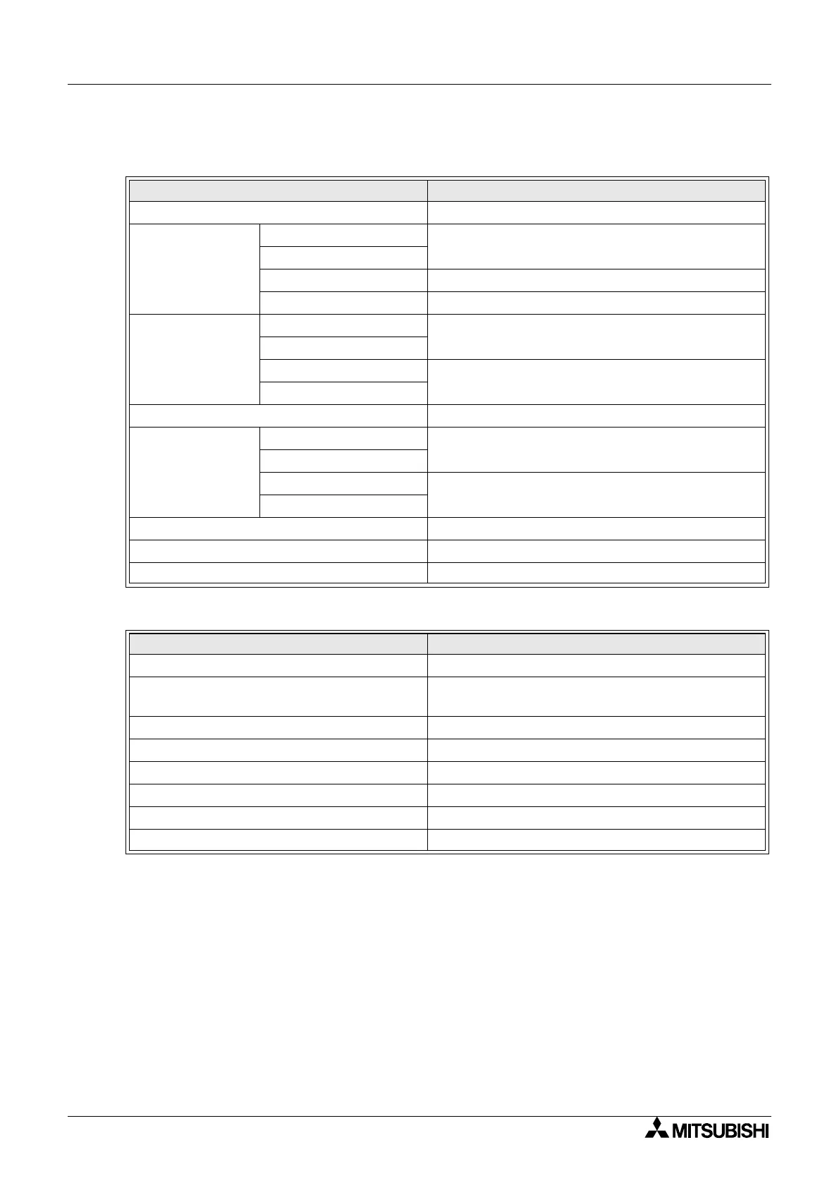
Tabelle 2.5: Technische Daten der Relais-Ausgänge
Beschreibung Technische Daten
Einschaltspannung 250V AC oder weniger, 30V DC oder weniger
Max. Ohmsche
Last
AL2-14MR-* (O01–O06)
8 A / Gesamt
AL2-24MR-* (O01–O04)
AL2-24MR-* (O05–O09) 2 A / Klemme (4 A / Gesamt)
AL2-4EYR (EO1–EO4) 2 A / Klemme
Lebenszyklus /
Ohmsche Last
AL2-14MR-* (O01–O06)
100000 Zyklen bei 8 A / 240V AC oder 24V DC
AL2-24MR-* (O01–O04)
AL2-24MR-* (O05–O09)
100000 Zyklen bei 2 A / 240V AC oder 24V DC
AL2-4EYR (EO1–EO4)
Minimale Last 50 mW (10 mA bei 5V DC)
Max. induktive Last
AL2-14MR-* (O01–O06)
249 VA (1/3 hp)/ 125V AC,
373 VA (1/2 hp) / 250V AC
AL2-24MR-* (O01–O04)
AL2-24MR-* (O05–O09)
93 VA (1/8 hp)/ 125V AC,
93 VA (1/8 hp) / 250V AC
AL2-4EYR (EO1–EO4)
Ansprechzeit
≤
10 ms
Betriebsanzeige LCD-Anzeige
Schaltkreisisolation über Relais
Tabelle 2.6: Technische Daten der Transistor-Ausgänge (Nur Source) fürAL2-4EYT
Beschreibung Transistor-Eigenschaften
Schaltspannung 5–24V DC (+20%,-5%)
Max. Ohmsche Last
1A / Klemme (8–24V DC),
0,1A / Klemme (5–8V DC)
Minimale Last 1,0 mA
Max. induktive Last 1 A / 24V DC (24 W)
Ansprechzeit Ein/Aus, Aus/Ein
≤
1ms
Leckstrom
≤
0,1 mA / 24V DC
Betriebsanzeige LCD-Anzeige
Schaltkreisisolation Optokoppler

 Loading...


