α
2 Simple Application Controllers
Wiring 4
ENG-25
ENG
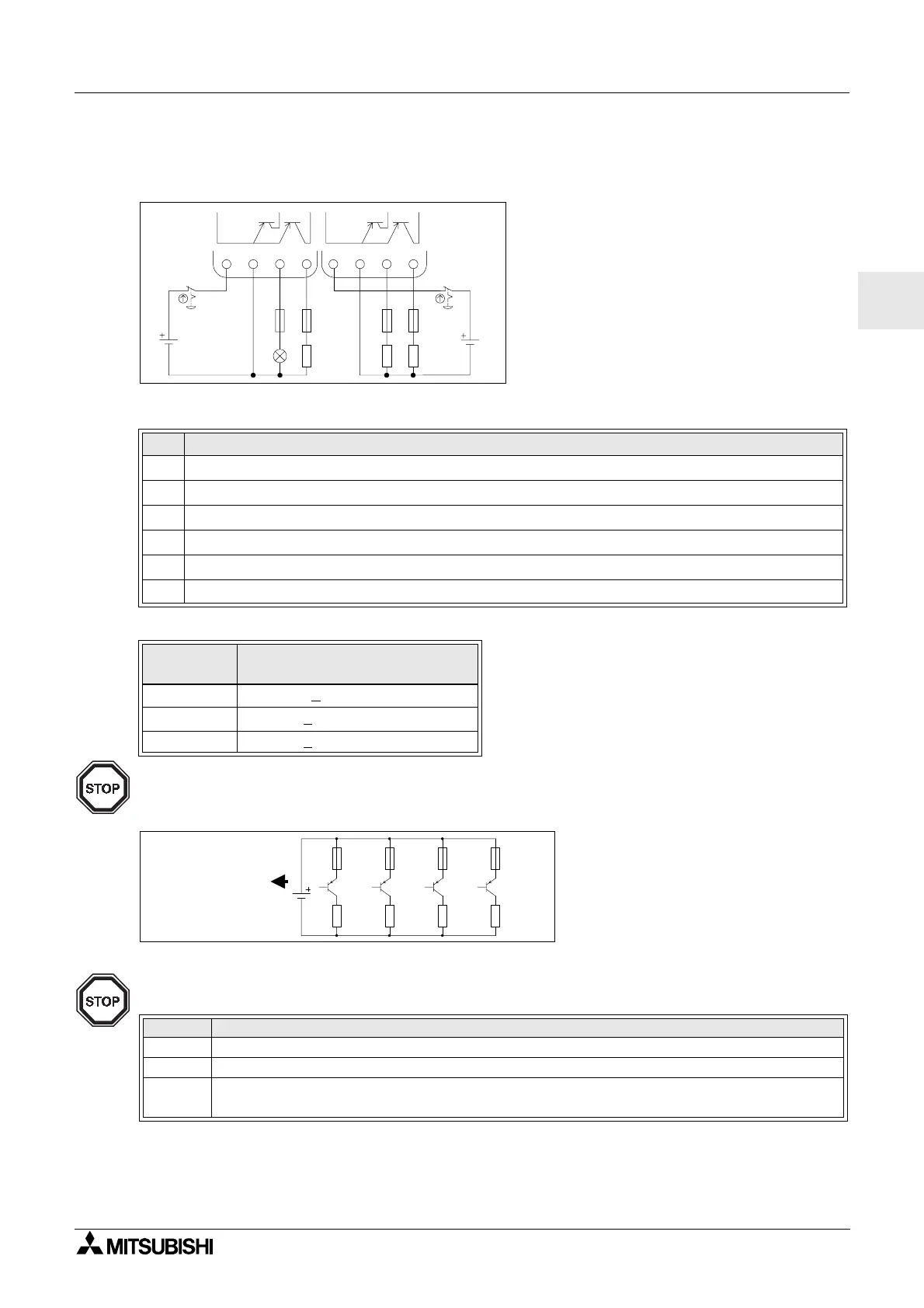
4.6.3 Transistor Output (Source or “+” Common Only) Wiring Diagram AL2-4EYT
Figure 4.11: Transistor Output (Source/ “+” Common Only) Wiring Diagram AL2-4EYT
*1 Power Source capacity
≥
Fuse size
×
2
Figure 4.12: Example Fuse Size Calculation
Note;
Table 4.13: Transistor Output Wiring
Ref. Item Description
1 DC Power Supply: 24V DC
2 Emergency Stop
3 Circuit Protection Device - See Table 4.14 for Specifications
4 Power Supply Terminal
5 Output Devices
6 DC Power Supply: 12V DC
Table 4.14: Transistor Output Circuit Protection Table
Circuit
Voltage
Circuit Protection (Fuse)
5V DC <
0.3A/Circuit
12V DC <
2.0A/Circuit
*1
24V DC < 2.0A/Circuit
*1
Table 4.15: Output Terminal Notes
Volt Output Terminal Notes
5 Each circuit can contain from one output terminal up to every output terminal.
12-24 Each circuit can contain from one output terminal up to every output terminal.
5,12,24
Using any combination of 5 Volt, 12 Volt, and 24 Volt outputs can be accomplished on the
same
α
2 Series Controller if separate circuits are used for each voltage level.
EO1 EO2 EO3 EO4
+
-
-+
Fuse
1A
12V,8A
(8A
≥
1A
×
2
×
4)
Fuse
1A
Fuse
1A
Fuse
1A
O01
O02 O03 O04

 Loading...


