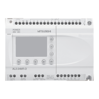
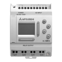
α
2-Steuerung
GER-ix
GER
Inhaltsverzeichnis
Sicherheitsrichtlinien ...................................................................GER-v
1. Einleitung.........................................................................................GER-1
1.1 Besonderheiten der
α
2-Steuerung:............................................................... GER-2
1.2 Verfügbare Modelle ....................................................................................... GER-3
1.3 Abmessungen und Bedienungselemente...................................................... GER-4
1.4 Systemkonfiguration ...................................................................................... GER-5
1.5 Programmier-Software .................................................................................. GER-5
2. Technische Daten ...........................................................................GER-7
2.1 Spannungsversorgung .................................................................................. GER-7
2.2 Eingänge ....................................................................................................... GER-8
2.3 Ausgänge .................................................................................................... GER-10
2.4 Umgebungsbedingungen ............................................................................ GER-11
3. Installation .....................................................................................GER-13
3.1 Installationshinweise.................................................................................... GER-13
3.2 Montage auf einer DIN Befestigungsschiene .............................................. GER-14
3.2.1 Montage ............................................................................................................ GER-14
3.2.2 Demontage........................................................................................................ GER-14
3.3 Direktmontage ............................................................................................. GER-15
3.4 Installation der Erweiterungsmodule ........................................................... GER-16
4. Verdrahtung...................................................................................GER-17
4.1 Hinweise zur Installationsverdrahtung......................................................... GER-17
4.2 Kabelgröße und Spezifikationen.................................................................. GER-18
4.3 Spannungsversorgung ................................................................................ GER-19
4.4 AC-Spannungsversorgung und Eingangsverdrahtung ................................ GER-20
4.4.1 AC-Spannungsversorgung und Eingangsverdrahtung...................................... GER-20
4.4.2 AL2-4EX-A2 Eingangsverdrahtung ................................................................... GER-20
4.5 DC-Spannungsversorgung und Eingangsverdrahtung................................ GER-21
4.5.1 DC-Spannungsversorgung und Source Eingangsverdrahtung
(gemeinsamer “+” Pol)....................................................................................... GER-21
4.5.2 AL2-4EX Source-Eingangsverdrahtung (gemeinsamer „+” Pol) ....................... GER-22
4.5.3 DC-Spannungsversorgung und Sink-Eingangsverdrahtung
(gemeinsame Masse)........................................................................................ GER-23
4.5.4 AL2-4EX Sink Eingangsverdrahtung (gemeinsame Masse) ............................. GER-24
4.6 Relais-/Transistor-Ausgangsverdrahtung .................................................... GER-25
4.6.1 Relaisausgangsverdrahtung „Hauptmodul“ (AC und/oder DC) ......................... GER-25
4.6.2 Relaisausgangsverdrahtung AL2-4EYR (AC und/oder DC).............................. GER-26
4.6.3 AL2-4EYT Transistor-Ausgangsverdrahtung
(nur Source <gemeinsamer „+”Pol>)................................................................ GER-27
5. Klemmenbelegung .......................................................................GER-29
6. AL2-EEPROM-2 ............................................................................GER-31
6.1 Installation ................................................................................................... GER-32

 Loading...


