20
1 MAIN switch
This is the main power switch. To use this recorder, set
this switch to ON. Otherwise, the POWER button on
the front panel of the recorder cannot turn on or off the
recorder.
2 <DX-TL308E> CAMERA connectors (1 to 8)
<DX-TL304E> CAMERA connectors (1 to 4)
Notice
• Do not connect superimposed voltage cameras
because they can cause damage to the recorder.
CAMERA IN connectors
BNC connectors to input camera video signals.
CAMERA OUT connectors
BNC connectors to output camera video signals.
When the MAIN switch is on, the camera video signals
input to CAMERA IN connectors are looped out to
these connectors.
3 VIDEO OUTPUT connectors
OUTPUT A VIDEO connector
BNC connector to output video signals to the monitor.
OUTPUT B VIDEO connector
BNC connector to output video signals to the second (B)
monitor. (
Page 24)
4 AC power socket
Use this socket to connect the supplied power cord.
Earth terminal is used for safety. Insert the power cord
of this recorder to the 100 to 240 V outlet with ground
terminal.
Notice
• When the power outlet does not have an earth
terminal, ask your dealer for grounding work (for pay).
Never connect the ground terminal of the power cord
to the gas pipe, water pipe, conductor rod and so on.
• Make sure to use the supplied power cord.
5 GND terminals
This terminal is used as common ground terminal.
6 XGA port (DX-TL308E only)
Port to output video signals to XGA monitor.
7 <DX-TL308E> ALARM IN terminals (1 to 8)
<DX-TL304E> ALARM IN terminals (1 to 4)
Terminals to input alarm signals. These terminals ac-
cept alarm signals once a second. However, when
multiple signals are input at the same time, not all the
signals may be accepted.
8 RS-232C connector
This connector is used to connect a host device
equipped with RS-232C connector (such as a personal
computer). This recorder can be controlled from other
devices via this connector.
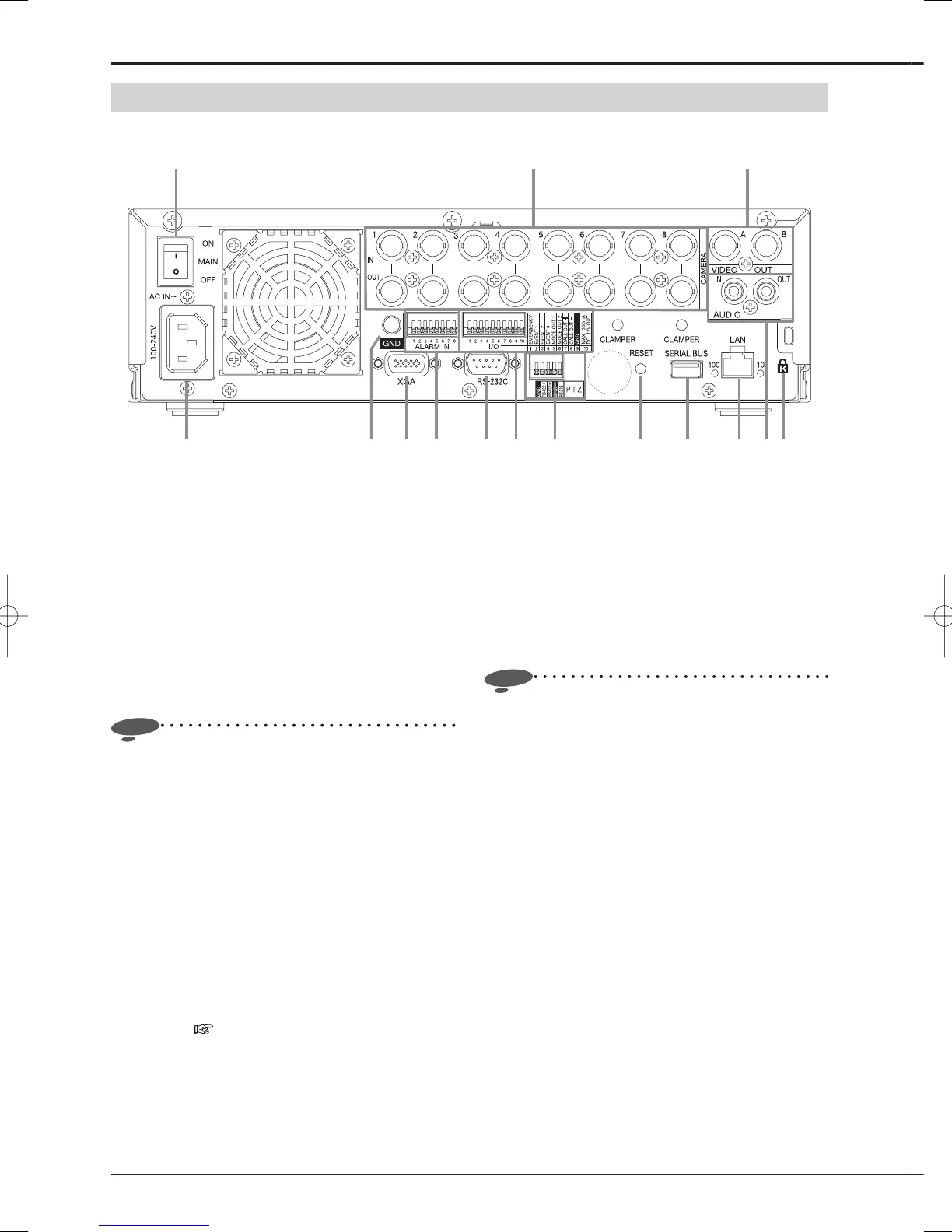
4 65 87 9 10 11 12 13 14 15
1 2 3
* This illustration shows an example of DX-TL308E.
Rear view
Major operations and their functions (continued)
 Loading...