Chapter 5 Installation
5–4
5-1-4 Tolerable load of axis
(1) Using the flexible coupling, set the axis core deviation to less than the tolerable radial load of the
axis.
(2) When using a pulley, sprocket and timing belt, select so that the loads are within the tolerable
radial load.
(3) A rigid coupling must not be used as it will apply an excessive bending load on the axis to break.
Servomotor Tolerable radial load Tolerable thrust load
HS-MF23 88N L=25 59N
HS-RF43/73 392N L=58 196N
HS-SF52/53/102/103 392N L=58 196N
HS-SF202 2058N L=79 980N
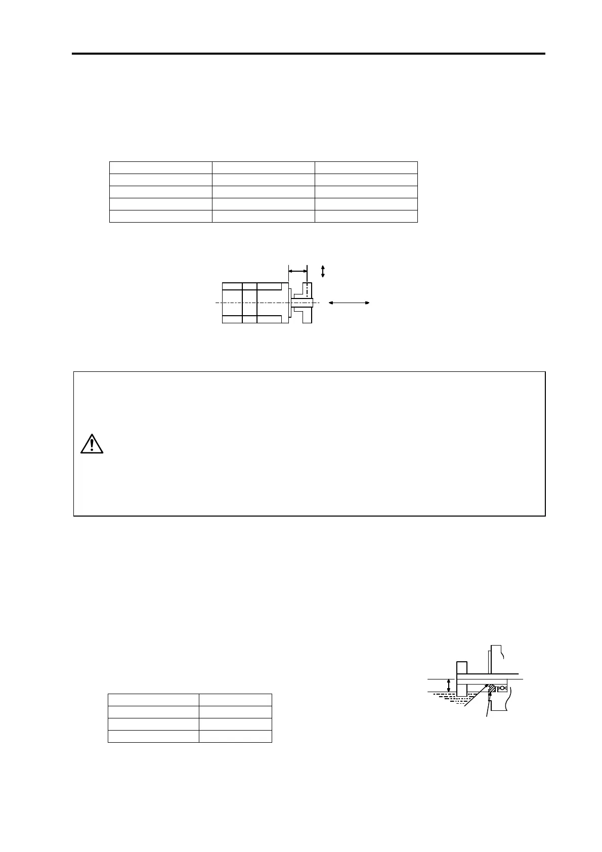
Caution: The symbols in the table follow the drawing below.
Radial load
Thrust load
L
L : Length from flange isntallation surface to center of load weight [mm]
CAUTION
1. When coupling with a ball screw, etc., use a flexible coupling, and keep the
shaft core deviation to below the tolerable radial load.
2. When installing the pulleys or gears on the motor shaft, the radial load will
increase as the diameter of these parts decreases. Consider this when
designing the machine.
3. When using a timing belt, adjust so that the radial load (double the tension)
generated from the tension is less than the values given above.
4. In a machine having a thrust load, such as a worm gear, provide a separate
bearing on the machine side so that the a load exceeding the tolerable
thrust load is not applied on the motor.
5. Do not use a rigid coupling as an excessive bending load will be applied on
the shaft and could cause the shaft to break.
5-1-5 Oil and waterproofing measures
(1) The servomotor does not have a precise water or oil-proof structure. The type (IP class) following
the IEC standards is indicated as the intelligent servomotor's protection type. These standards are
the short-time performance standards, so make sure that the motor surface is not subject to fluids
and that fluids do not accumulate. If cutting oil, etc., could enter, always provide a protective
cover. Always consider the cover seams, edges, shapes and dimensions. Note that the IP class
does not indicate the corrosion resistance level.
(2) When a gear box is installed on the servomotor, make sure that
the oil level height from the center of the shaft is higher than the
values given below. Open a breathing hole on the gear box so
that the inner pressure does not rise.
Servomotor Oil level (mm)
HS-MF23 12
HS-RF43, 73, -SF103 20
HS-SF202 25
Servomotor
Gear
Lip
Oil level
Oil seal
 Loading...