Chapter 8 Adjustment
8–2
8-1 Measurement of adjustment data
The intelligent servomotor has a function to D/A output the various control data. To adjust the servo
and set the servo parameters that match the machine, it is necessary to use the D/A output and
measure the internal status of the servo. Measure using a hi-coder, synchroscope, etc.
8-1-1 D/A output specifications
<Output specifications>
No. of channels : 1ch.
Output cycle : 888µsec (min. value)
Output precision : 8bit
Output voltage range : 0V to 2.5V to 5V
Output pins : On intelligent servo I/F unit
Output scale setting : ±1/256 to ±128 times
Output resistance : 1kΩ
<Output function>
• Offset amount adjustment function
• Output clamp function
• Low path filter function
<Measurement method>
Connect the measuring instrument to the I/F unit check pin. When observing the waveform, turn the
I/F unit DIP switch OFF.
Note that the DIP switch must be turned ON when the power is turned ON. Do not connect a
measuring instrument having a low input impedance when turning the power ON.
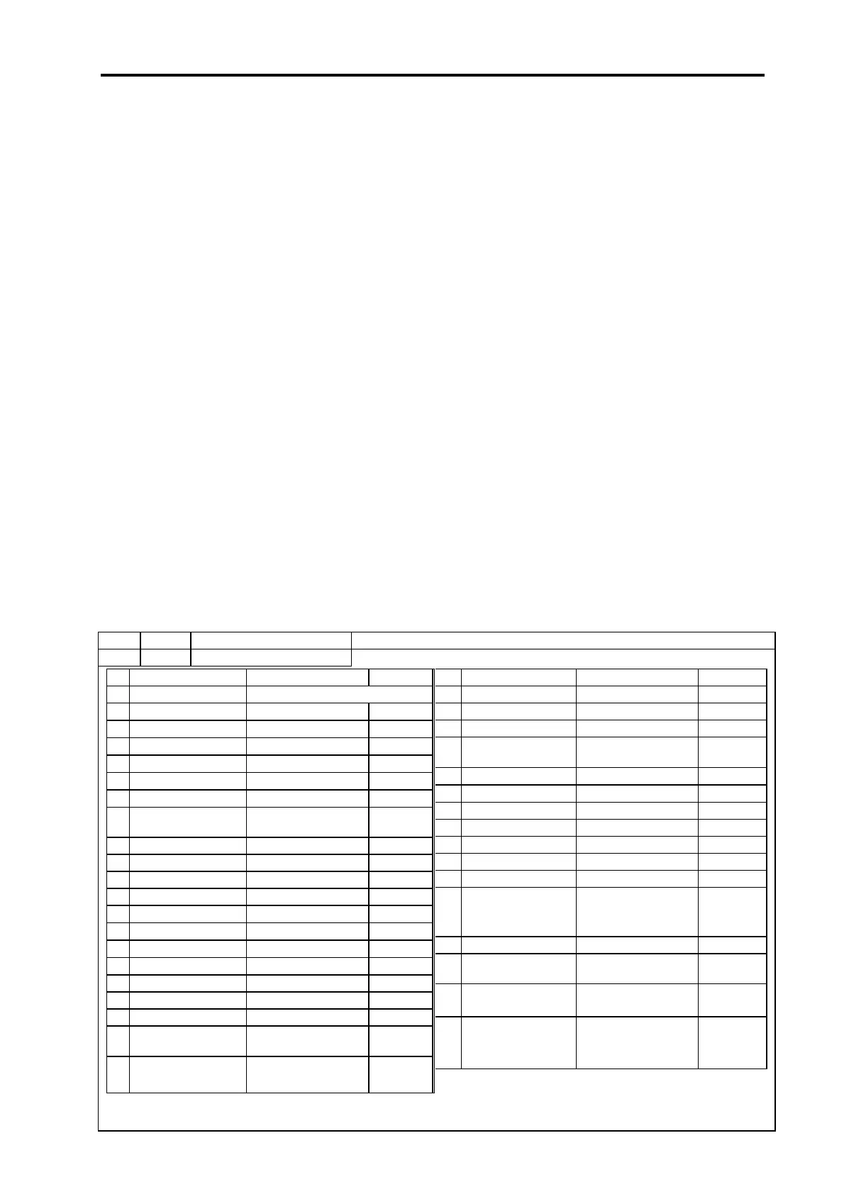
8-1-2 Setting the output data
No. Abbrev. Parameter name Explanation
SV061 DA1NO D/A output channel 1 data No. Input the No. of the data to be output to each D/A output channel.
No. Output data Standard output unit
Output cycle
21 Motor load level 100%/1.25V 113.7 msec
22 Amplifier load level 100%/1.25V 113.7 msec
23
Regenerative load
level
100%/1.25V 910.2 msec
24 PN bus wire voltage 200V/V (1/200)
888 µsec
25 Speed cumulative item
–
888 µsec
26 Cycle counter 0–125V
888 µsec
27 – 3.55 msec
28 –
29 – 3.55 msec
30 – 3.55 msec
31
to
99
–
100
5 V test output – –
101
Saw-tooth wave test
output
1.25 to 3.75V
Cycle 113.7 msec
888 µsec
102
Rectangular wave test
output
2.5 to 3.75V
Cycle 227.5 msec
888 µsec
103
Setting prohibited
No.
Output data Standard output unit
Output cycle
0 0 V test output For offset amount adjustment
1 Speed feedback 2000rpm/1V
888 µsec
2 Current feedback Rated current/0.5V
888 µsec
3 Speed command 2000rpm/1V
888 µsec
4 Current command Rated current/0.5V
888 µsec
5 V-phase current value 40A/V
888 µsec
6 W-phase current value 40A/V
888 µsec
7
Estimated disturbance
torque
Rated current/0.5V
888 µsec
8 –
9 –
10 –
11 Position droop 4 mm/V 3.55 msec
12
Position droop(×10) 400 µm/V
3.55 msec
13
Position droop(×100) 40 µm/V
3.55 msec
14
Feedrate (F∆T)
40000 (mm/min)/V
888 µsec
15
Feedrate (F∆T×10)
4000 (mm/min)/V
888 µsec
16 – 3.55 msec
17 – 3.55 msec
18 – 3.55 msec
19
q axis current
cumulative value
–
888 µsec
20
d axis current
cumulative value
– 888 µsec
 Loading...