7.2.2
Programmable controller-related signals
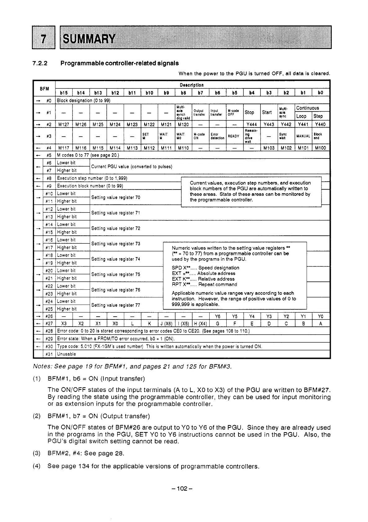
When the power
to
the
PGU
is turned
OFF,
all data is cleared.
BFM
Detcrlptlon
b15
I
b14
I
b13
I
b12
I
bll
I
b10
I
b9
1
b8
I
b7
1
b6
I
b5
I
b4
I
b3
I
b2
I
bl
I
bO
-
#O
Block desianation
10
to
99)
axis
Step Loop
aync
dog vakd
sris
Start
!;ye
transler transler
synch
Input
Output
Multi.
Continuous
Mutfi-
-
#1
-
-
- - -
-
-
#2
Y440
Y441
Y442 Y443
Y444
-
-
-
M120
M121 M122 M123 M124 M125 M126 M127
SET Error
Made
WAF
WAIT
Remain.
in9
wail
-
#3
M100 M101 M102 M103
- - - -
M110
M111
M112 M113
M114
M115
M116 M117
-
114
-
-
- -
-
M
drwr
READY
detection
ON
MO
M
-
:2k
MANUAL
iT
-
#5
M codes
0
to
77
(see
page
20.)
CI
#6
Higher bit
#7
Lower
bit
Current
PGU
value
(converted
to
pulses)
-
Execution
block
number
(0
to
99)
#9
+
Execution
step
number
(0
to
1,999)
#8
Current values, execution step numbers, and execution
-
block numbers
of
the
PGU
are automatically written to
-
#I
0
Lower
bit
these areas. State
of
these areas can be monitored by
#I
1
Higher
bit
#I3
Lower
bit
#12
-
the programmable controller.
Higher
bit
-
Setting
value
register
70
-
Setting
value
register
71
-+
#I4
1
Lower
bit
#I5
I
Higher
bit
Setting
value
register
72
Setting
value
register
73
SPD
X*.....
Speed designation
WT
P.....
Absolute address
WT
Kf*.....
Relative address
RPT
X*.....
Repeat command
Applicable numeric value ranges vary according
to
each
instruction. However, the range
of
positive values of
0
to
Setting
value
register
77
999,999
is applicable.
-
1
#30
]Type
code:
5,010 (FX.lGM's
used
number)
This
is
written
automatically
when
the
power
is
turned
ON.
1
#31
1
Unusable
Notes:
See
page 19
for
BFM#l, and pages 21 and 125
for
BFM#3.
(1) BFM#l,
b6
=
ON (Input transfer)
The ON/OFF states
of
the input terminals (A to
L,
X0 to X3)
of
the PGU are written to BFM#27.
By reading the state using the programmable controller, they can be used for input monitoring
or as extension inputs for the programmable controller.
(2)
BFM#l, b7 = ON (Output transfer)
The ON/OFF states of BFM#26 are output to YO to Y6 of the PGU. Since they are already used
in the programs in the PGU,
SET
YO
to
Y6 instructions cannot be used
in
the PGU. Also, the
PGU's digital switch setting cannot be read.
(3)
BFM#2,
#4:
See page
28.
(4)
See page 134 for the applicable versions of programmable controllers.
-
102
-
 Loading...


