~~
2.2
When Using the Programmable Controller with a PGU
2.2.1
Signals related to the programmable controller
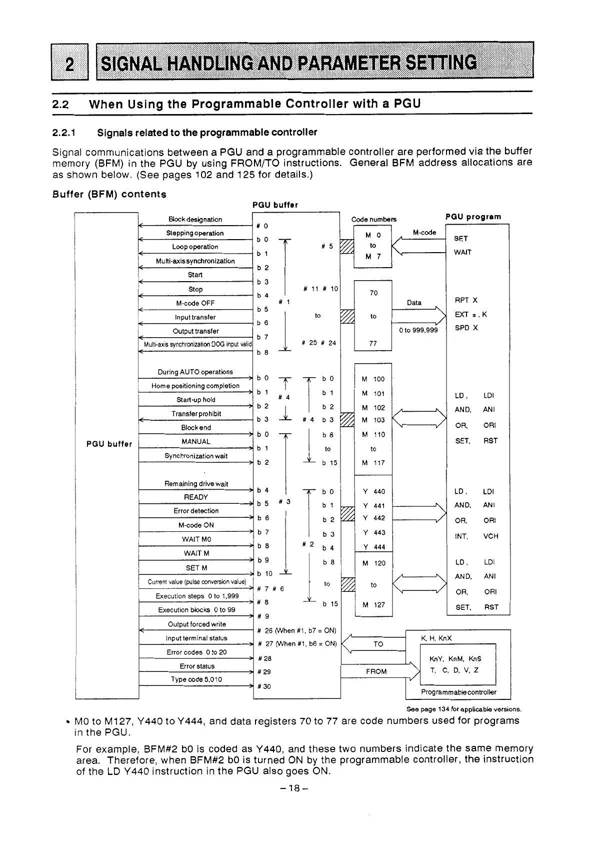
Signal communications between a PGU and a programmable controller are performed via the buffer
memory (BFM) in the PGU by using FROM/TO instructions. General BFM address allocations are
as shown below. (See pages 102 and 125 for details.)
Buffer
(BFM)
contents
PGU
buffer
#
11
#
10
Remaining drive wait
READY
Error detection
M-code
ON
WAIT
MO
WAIT
M
SET
M
>b5 #3
+
>b9
>
b 10
Execution blocks
0
to
99
b
15
#
26 (When #1, b7
=
ON)
#
27 (When #1, b6
=
ON)
Error codes
0
to
20
Error status
Type code
5.01
0
Code numbets
PGU
program
4
to
p
0
to 999,999
I
77
I
M
100
M
101
M 102
M 103
M
110
to
M
117
E
2
J
I
Y
440
Y
441
4
Y
442
Y
443
Y
444
M 120
2
J
2
J
to
M
127
SET
WAIT
RPT
X
MT
+,K
SPD
X
LD,
LDI
AND,
ANI
OR,
OR1
SET,
RST
LD,
LDI
AND,
ANI
OR,
OR1
INT,
VCH
LD.
LDI
AND,
ANI
OR,
OR1
SET,
RST
K
H,
KnX
KnY,
KnM,
KnS
T,
C,
D, V,
Z
Programmablecontrollr
See page 134 for applicable versions
MO to M127, Y440 to Y444, and data registers
70
to 77 are code numbers used for programs
in the PGU.
For example, BFM#2 bO is coded as Y440, and these two numbers indicate the same memory
area. Therefore, when BFM#2 bO is turned
ON
by the programmable controller, the instruction
of the
LD
Y440 instruction in the PGU also goes
ON.
-
18-
 Loading...


