2.3.6
Setting
of
the operating
mode
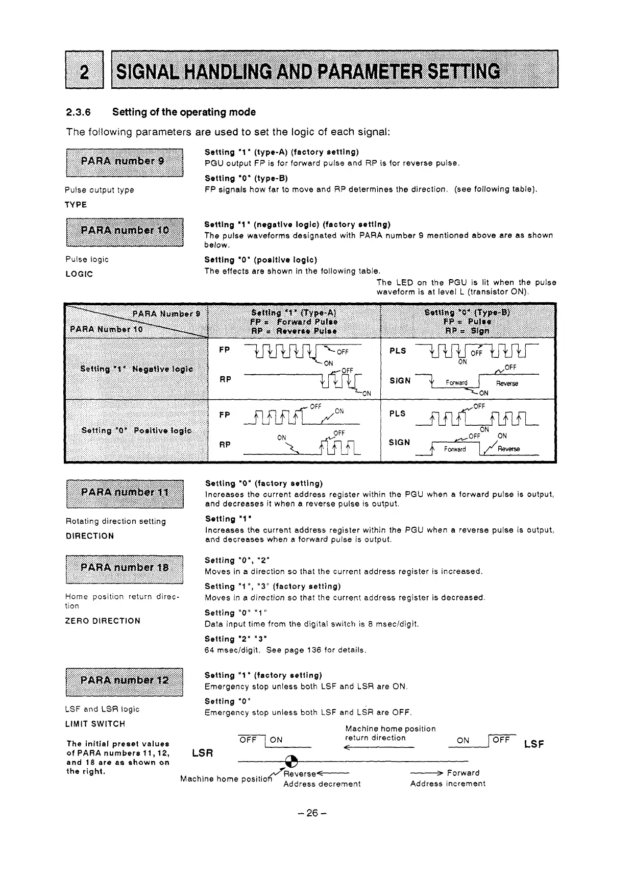
The
following parameters
are
used
to
set the
logic
of
each signal:
Pulse output type
TYPE
FP
signals how far to move and
RP
determines the direction. (see following table).
Pulse logic
LOGIC
Setting
'0'
(positive logic)
The effects are shown in the following table.
The
LED
on the PGU
is
lit when the pulse
waveform is at level
L
(transistor
ON).
Rotating direction setting
DIRECTION
Home
position return direc-
tion
ZERO
DIRECTION
LSF
and
LSR
logic
LIMIT SWITCH
The initial preset values
of
PARA
numbers
11,12,
and
18
are
as
shown
on
the right.
Setting
"0"
(factory setting)
Increases the current address register within the PGU when a forward pulse
is
output,
and decreases it when
a
reverse pulse is output.
Setting '1
'
Increases the current address register within the PGU when a reverse pulse is output,
and decreases when a forward pulse is output.
Setting
"Om,
"2"
Moves in a direction
so
that the current address register is increased.
Setting
"1
'I,
"3"
(factory setting)
Moves in a direction
so
that the current address register is decreased
Setting
"0"
"1
I'
Data input time from the digital switch is
8
msec/digit
Setting "2"
"3'
64
msec/digit. See page
136
for details.
Setting
"1
"
(factory setting)
Emergency stop unless both
LSF
and
LSR
are
ON.
Setting
"0"
Emergency stop unless both
LSF
and
LSR
are
OFF.
Machine home Dosition
OFF
ON
return direction
ON
I
OFF
LSF
LS
R
7
A
Machine home positio (RTverse-
Address decrement
-26-
-
Forward
Address increment
 Loading...


