6.2.4
Connection
of
general-purpose output terminals
Output specifications
I.
-
.
-
in~r.n~power-.
-
.
-
.
-.
-
.
-. -.
-
.
-
.
-
.
-.
I
I
COM3
supply for control
COM6
-
24V
External power supply
(5
to
24
VDC)
I
5w
I
I
OUT
:
Load
(0.3
A
or more)
PGU
I
Output terminal:
A
terminal common to all outputs is used.
Use a smooth power supply of
5
to 24V DC for the external power supply for load driving.
Circuit insulation:
The circuit built in the
PGU
is isolated from the output transistor with a photo-coupler, however,
the transistor base current is supplied by the built-in 24V DC power supply used for the
general-purpose inputs.
Operation lights:
The output LED indicator is arranged in the photo-coupler drive circuit.
The output transistor is turned ON when the LED is turned
ON,
Response time:
The switching time from
ON
to
OFF
and
OFF
to
ON
is less than
1
msec.
Output current:
It
is possible to flow a max. of 0.3A current per 1 output point.
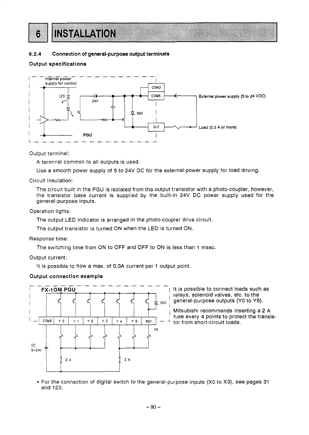
Output connection example
'
-Fx-1
GM
PGU-
I
It is possible to connect loads such as
I
I
'
relays, solenoid valves, etc. to the
I
5c
5ov
.
general-purpose outputs
(YO
to
Y6).
I
I
'
Mitsubishi recommends inserting a 2 A
1
fuse every 4 points to protect the transis-
1.
I.-[
COM6/
Yo
I
YI
I
Y2
I
Y3
I
y4
1
Y5
I
ROY
].-.A
tor from short-circuit loads.
Y6
<'
<>
<'
DC
-
5-24v
T
r-
For the connection
of
digital switch to the general-purpose inputs (X0
to
X3), see pages 31
and 123.
-90-
 Loading...


