The sections
so
far have described the functions of the
FX-1
GM
and its programming procedures.
Now, let's step forward from desk theory to the practical use of the machine.
This section explains the installation, wiring, maintenancelinspection, and troubleshooting
of the
main unit.
Mitsubishi recommends that this information be delivered to the end user.
6.1
Installing in the Panel
6.1.1
General installation and wiring items
Installation dimensions
[Mounting to DIN rails]
The
PGU
can be mounted to a DIN46277 DIN rail
(35
mm wide) with no additional work.
To
remove the unit, pull down the hook on the DIN rail and remove the unit.
Do not attempt to mount the unit on the surface
of
the floor or ceiling since doing
so
blocks
Thread pitches
of
the screw holes
(M4)
for direct mounting are as given
in
the table below.
the ventilation system. Be sure to mount the unit on the wall.
FX-16M, 24M
FX-32M
FX-48M
FX-64M
FX-OOM
FX-128M
140
150
220
260
320
390
FX-32€,
FX-1GM
FX-48E
I
1
50
220
*
FX-8E, 0EX,
8EY
FX-l6E[ 1-V
FX-l6E(
I-C
*
FX-l6EX, 16EY
*
FX2-24EI
35
35
35
63
35
FX2-40AP, 40AW
35
FX-232AW
35
FX-8AV
35
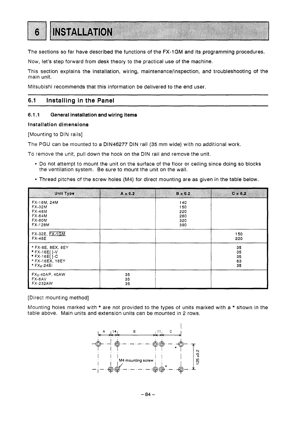
[Direct mounting method]
Mounting holes marked with
*
are not provided to the types of units marked with a
*
shown
in
the
table above. Main units and extension units can be mounted in
2
rows.
-84-
 Loading...


