1 - 18
MELSEC-Q
1 PRODUCT OUTLINE
1.1.5 Outline design of positioning system
The outline of the positioning system operation and design, using the QD75, is shown
below.
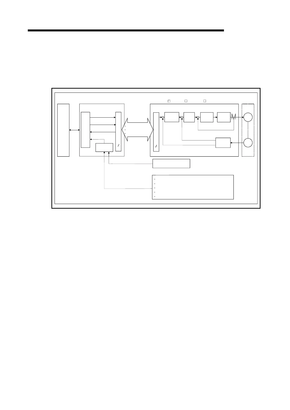
(1) Positioning system using QD75
PLC
CPU
QD75
Read,
write
and
etc.
OS
Positioning command
Control command
Monitor data
Positioning command
Control command
Monitor data
Positioning
control
Speed
control
Current
control
Inverter
Current feedback
Speed feedback
Position feedback
Interface
Servo
motor
M
PLG
FLS (Upper limit signal)
RLS (Lower limit signal)
CHG (External command signal/switching signal)
STOP (Stop signal)
DOG (Near-point dog signal)
External output signal (Refer to the section 3.3.2)
Manual puse generator
A-phese/B-phese
SSCNET
S
S
C
N
E
T
I
F
Interface
S
S
C
N
E
T
I
F
-
+
-
+
-
+
-
+
MR-H-BN/MR-H B/MR-J2- B/MR-J2S- B/MR-J2-Jr/MR-J2M-B
Fig. 1.2 Outline of the operation of positioning system using QD75

 Loading...