13 - 7
MELSEC-Q
13 COMMON FUNCTIONS
13.4 External I/O signal logic switching function
This function switches the signal logic according to the external equipment connected
to the QD75.
For the system in which b-contact, upper limit switch, and lower limit switch are not
used, the parameter logic setting can be controlled without wiring if it is changed to a
"positive logic".
When the upper limit switch, and lower limit switch are used, ensure to use them with
b-contact.
The details shown below explain about the "External I/O signal logic switching
function".
[1] Parameter setting details
[2] Precautions on parameter setting
[1] Parameter setting details
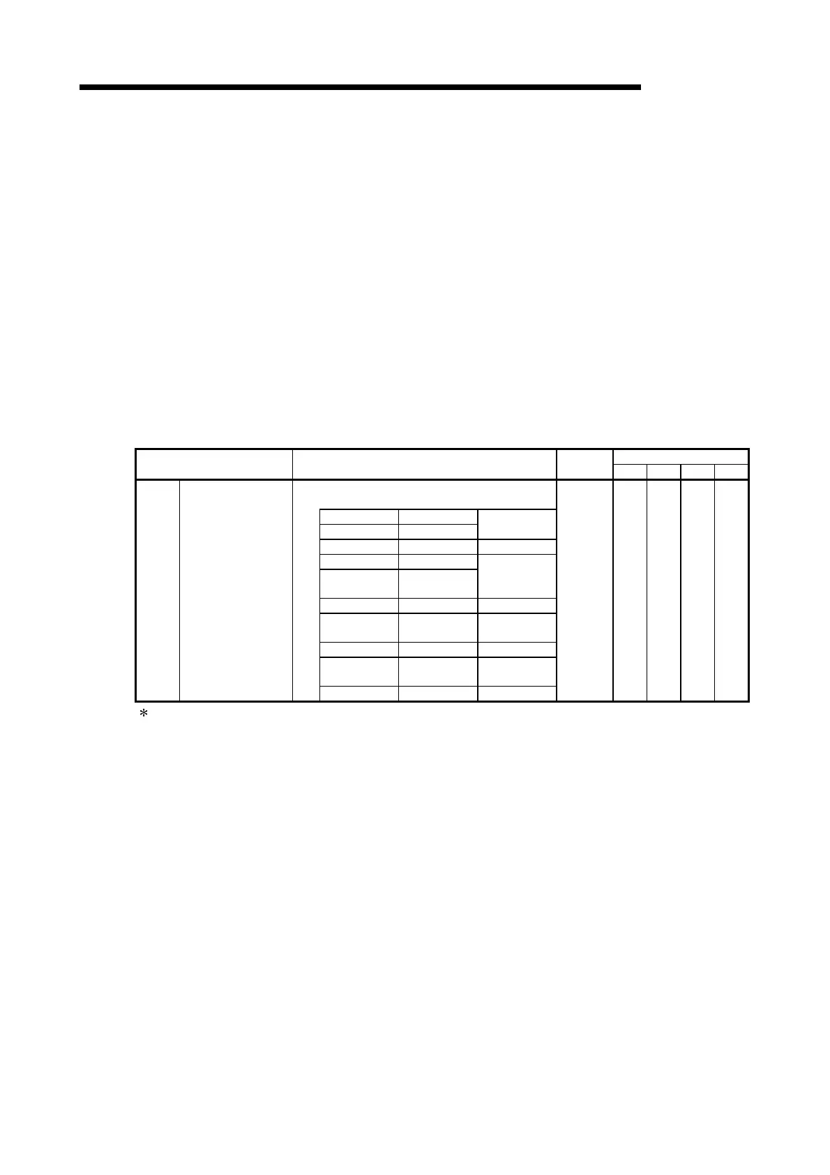
To use the "External I/O signal logic switching function", set the parameters
shown in the following table.
Buffer memory address
Setting item Setting details
Factory-set
initial value
Axis 1 Axis 2 Axis 3 Axis 4
• Selection of logic of signals input from external source to
QD75
b0 Lower limit
b1 Upper limit
0: Negative logic,
1: Positive logic
b2 Not used Set "0".
b3 Stop signal
b4
External
command
0: Negative logic,
1: Positive logic
b5 Not used Set "0".
b6 Near-point signal
0: Negative logic,
1: Positive logic
b7 Not used Set "0".
b8
Manual pulse
generator input
0: Negative logic,
1: Positive logic
Pr.22
Input signal logic
selection
b9 to b15 Not used Set "0".
0 31 181 331 481
Refer to section 5.2 "List of parameters" for the information on detail settings.
[2] Precautions on parameter setting
(1) The I/O signal logic switching parameters are validated when the PLC
READY signal [Y0] is turned OFF to ON. (The logic is negative right after
power-on.)
(2) If each signal logic is set erroneously, the operation may not be carried out
correctly.
Before setting, check the specifications of the equipment to be used.

 Loading...