3 - 19
MELSEC-Q
3 SPECIFICATIONS AND FUNCTIONS
3.4.4 Interface internal circuit
The outline diagrams of the internal circuits for the QD75M1 external device
connection interface are shown below.
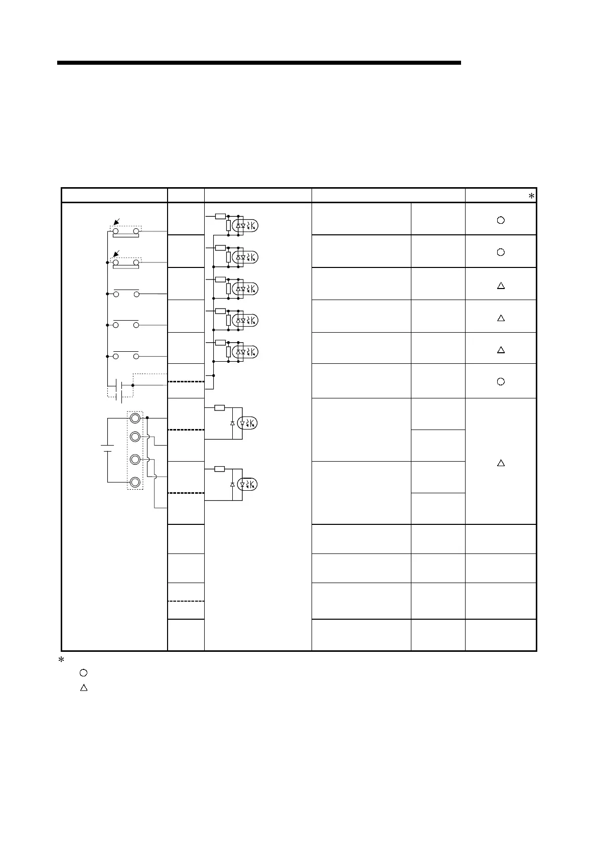
(1) Input
External wiring Pin No. Internal circuit Signal name Need for wiring
1A1 Upper-limit LS signal FLS
1A2
Lower-limit LS signal RLS
1A3
Near-point dog signal DOG
1A4
Stop signal STOP
1A5
External command
signal/switching signal
CHG
1A6
1A7
Common COM
(+)
1A19
PULSER A+
(–)
1B19
Manual pulse generator
A phase
PULSER A–
(+)
1A20
PULSER B+
(–)
1B20
Manual pulse generator
B phase
PULSER B–
1A11
— — —
1A12
— — —
1A8
1A9
— — —
24VDC
5VDC
5V
0V
A
B
Manual pulse
generator
(MR-HDP01)
When Upper-limit
LS is not used
When Lower-limit
LS is not used
1A10
— — —
: The symbols in Need for wiring column indicate the following meanings:
•
: Wiring is necessary for positioning.
•
: Wiring is necessary depending on the situation.

 Loading...