4 - 3
MELSEC-Q
4 INSTALLATION, WIRING AND MAINTENANCE OF THE PRODUCT
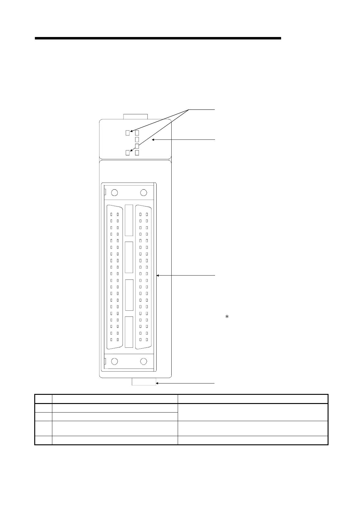
4.1.2 Names of each part
(1) The part names of the QD75 are shown below:
For QD75M4
(1) RUN indicator LED, ERR indicator LED
(40-pin connector)
AX1: Axis 1
QD75M4
AX1
AX2
AX3
AX4
RUN
ERR AX4
AX3
AX2
AX1
QD75M4
(2) Axis display LED
(3) External device connector
AX2: Axis 2
AX3: Axis 3
AX4: Axis 4
Refer to "Section 3.4.2 Signal layout for external
device connection connector" for details.
(4) SSCNET cable connector
No. Name Details
(1) RUN indicator LED, ERR indicator LED
(2) Axis display LED (AX1 to AX4)
Refer to the next page.
(3) External device connector
A connector connected with a drive unit, mechanical system
input, or manual pulse generator.
(4) SSCNET cable connector A connector connected with servo amplifier.

 Loading...