1 - 12
MELSEC-Q
1 PRODUCT OUTLINE
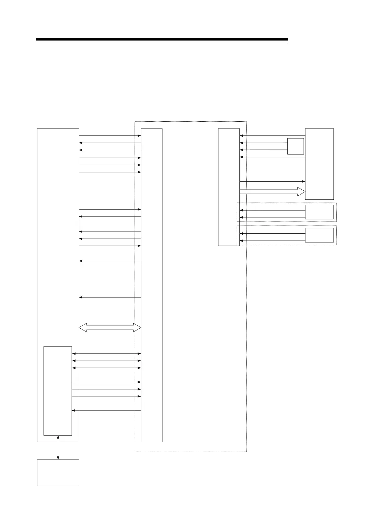
1.1.5 Communicating signals between QD75 and each module
The outline of the signal communication between the QD75 and CPU module,
peripheral device and drive unit, etc., is shown below.
(A peripheral device communicates with the QD75 via the CPU module to which it is
connected)
PLC READY signal
QD75 READY signal
Positioning start signal
Positioning complete signal
BUSY signal
Axis stop signal
Start complete signal
Error detection signal
Upper/lower limit signal
External
signal
Near-point dog signal
Zero signal
Drive unit READY signal
Drive
unit
Manual pulse generator A-phase
Deviation counter clear
Pulse train
Manual pulse
generator
External
interface
QD75
Data write/read
Y0
X0
Y8,YA,YC,YE
External
signal
Stop signal
External command signal
Positioning data write/read
Block start data write/read
Operation monitor
Parameter write/read
JOG/Inching operation
Positioning operation (test)
OPR operation (test)
Peripheral
device
Peripheral
device
interface
Y9,YB,YD,YF
Syncronization flag
Forward run JOG start signal
Reverse run JOG start signal
M code ON signal
Manual pulse generator B-phase
Execution prohibition flag
Y14,Y15,Y16,Y17
CPU module
X1
Y10,Y11,Y12,Y13
X14,X15,X16,X17
XC,XD,XE,XF
X10,X11,X12,X13
Y4,Y5,Y6,Y7
X4,X5,X6,X7
X8,X9,XA,XB
Interface
with
CPU
module
 Loading...
