13 - 8
MELSEC-Q
13 COMMON FUNCTIONS
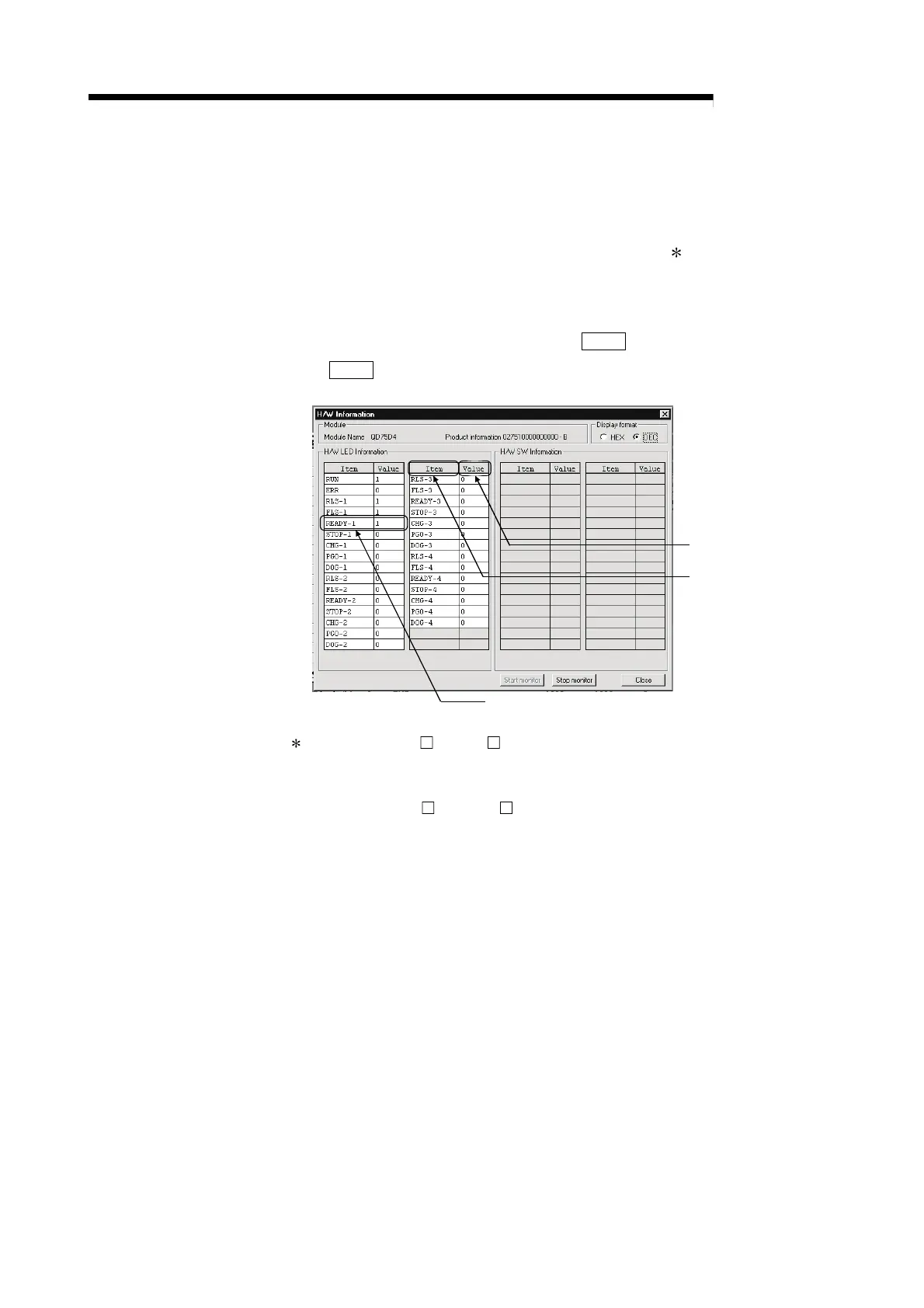
13.5 External I/O signal monitor function
The "external I/O signal monitor function" monitors the module's information and
external I/O signal monitor information in the module's detailed information which
can be displayed on the system monitor of GX Developer
1
.
The information that can be monitored are the module's information (same as the
QD75 front "RUN", "ERR" LED indicators) and the following external I/O signals.
(Set the logic of the external I/O signals in "
Pr.22
Input signal logic selection"
and "
Pr.23
Output signal logic selection".)
Indicates that Drive unit ready of axis 1 is ON.
0:OFF, 1:ON
Axis-by-axis external I/O
signals and module RUN,
ERR LEDs
1: For the QD75P /QD75D , this function is available in GX Developer
(SW6D5C-GPPW-E or later). For details, refer to GX Developer Operating
Manual.
For the QD75P
N/QD75D N, external I/O signals cannot be monitored on
GX Developer. Use the system monitor of GX Works2. For details on the
system monitor of GX Works2, refer to GX Works2 Version 1 Operating
Manual (Common).
 Loading...
