4 - 3
MELSEC-Q
4 INSTALLATION, WIRING AND MAINTENANCE OF THE PRODUCT
4.1.2 Names of each part
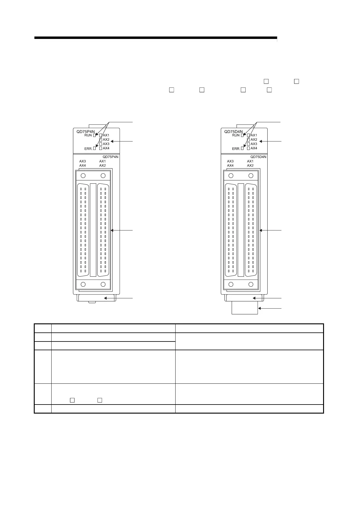
(1) The part names of the QD75 are described with the QD75P N/QD75D N as an
example. The QD75P
N/QD75D N and QD75P /QD75D are different in the
indication of their model names and serial numbers
1)
2)
3)
5)
1)
2)
3)
4)
5)
QD75P4N QD75D4N
No. Name Details
1) RUN indicator LED, ERR indicator LED
2) Axis display LED (AX1 to AX4)
Refer to the next page.
3) External device connector
Connector for connection with the drive unit, mechanical
system input or manual pulse generator. (40-pin connector)
AX1: Axis 1, AX2: Axis 2, AX3: Axis 3, AX4: Axis 4
For details, refer to Section 3.4.2 "Signal layout for external
device connection connector".
4)
Differential driver common terminal
(Differential driver output system (the
QD75D
N/QD75D ) only)
Terminal connected to the differential receiver common of the
drive unit. For details, refer to Section 4.3.2 "Wiring of the
differential driver common terminal".
5) Serial number plate Indicates the serial number of the QD75
 Loading...
