S350 Series 24-Port (PoE+) and 48-Port Gigabit Ethernet Smart Managed Pro Switches
Monitor the System User Manual313
Description: <15>Aug 24 05:34:05 STK0 MSTP[2110]: mspt_api.c(318)
237 %% Interface 12 transitioned to root state on message age
timer expiry
The previous log message example indicates a user-level message (1) with severity 7
(debug) on a system that is not stacked and generated by component MSTP running in
thread ID 2110 on
Aug 24 05:34:05 by line 318 of file mstp_api.c. This is the 237th
message logged. Messages logged to a collector or relay via syslog support an identical
format as the previous message.
Manage the Server Log
You can let the switch send log messages to remote logging hosts.
You must enable the server log on the switch and specify one or more remote syslog hosts.
Enable the Server Log
To enable the server log:
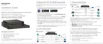
1. Connect your computer to the same network as the switch.
You can use a WiFi or wired connection to connect your computer to the network, or
connect directly to a switch that is off-network using an Ethernet cable.
2. Launch a web browser.
3. In the address field of your web browser, enter the IP address of the switch.
If you do not know the IP address of the switch, see
Discover or Change the Switch IP
Address on page 12.
The login window opens.
4. Enter the switch’s password in the Password
field.
The default password is password.
The System Information page displays.
5. Select Monitoring > Logs > Server Log.
The Server Log Configuration page displays.
6. In the Server Log Configuration section, select one of the following
Admin Status radio
buttons:
•
Enable. Send log messages to all configured hosts (syslog collectors or relays) using
the values configured for each host.
• Disable. Stop logging to all syslog hosts. Disable means no messages are sent to
any collector or relay.
7. In the
Local UDP Port field, specify the port on the switch from which syslog messages
must be sent. The Local UDP port values are 1 to 65535.
8. Click the Apply
button.
 Loading...