S350 Series 24-Port (PoE+) and 48-Port Gigabit Ethernet Smart Managed Pro Switches
Configure Switching User Manual144
The switch support the following spanning tree versions:
• CST. Common STP. For information on configuring CST, see Configure and View the
CST Settings on page 146 and Configure and View the CST Port Settings on page 148.
• MSTP. Multiple Spanning T
ree Protocol (MSTP, also referred to as MST) supports
multiple instances of spanning tree to efficiently channel VLAN traffic over different
interfaces. For information on configuring MSTP, see
Manage MST Settings on page 153
and
Configure and View the Port Settings for an MST Instance on page 155.
• RSTP. Rapid STP. Each instance of the spanning tree behaves in the manner specified in
IEEE 802.1w
, Rapid Spanning Tree (RSTP), with slight modifications in the working but
not the end effect (chief among the effects is the rapid transitioning of the port to the
forwarding state). For information on viewing the RSTP state, see
View Rapid STP
Information on page 152.
The difference between the RSTP and the traditional STP (IEEE 802.1D) is the ability to
configure and recognize full-duplex connectivity and ports that are connected to end
stations, resulting in rapid transitioning of the port to the forwarding state and the
suppression of
T
opology Change Notification. These features are represented by the
parameters pointtopoint and edgeport. MSTP is compatible with both RSTP and STP. It
behaves in a way that is appropriate for STP and RSTP bridges. An MSTP bridge can be
configured to behave entirely as an RSTP bridge or an STP bridge.
Note: For two bridges to be in the same region, the force version must be
802.1s and their configuration names, digest keys, and revision levels
must match. For additional information about regions and their effect
on network topology, refer to the IEEE 802.1Q standard.
Configure the STP Settings and View the STP Status
You can configure the STP settings and view the STP status on the switch.
To configure the STP settings and view the STP status:
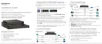
1. Connect your computer to the same network as the switch.
You can use a WiFi or wired connection to connect your computer to the network, or
connect directly to a switch that is off-network using an Ethernet cable.
2. Launch a web browser.
3. In the address field of your web browser, enter the IP address of the switch.
If you do not know the IP address of the switch, see
Discover or Change the Switch IP
Address on page 12.
The login window opens.
4. Enter the switch’s password in the Password
field.
 Loading...