- A ・ -
logo_Q0650_forGraphic
071004_Gdesign_ito
VBA21001-R.3753.A
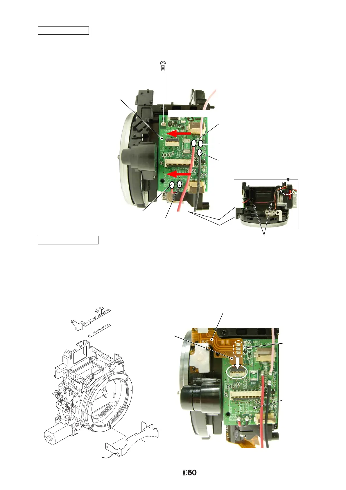
SB SW unit (#B1012)
Solder bridge ×3
Relay-PCB
#607
Fig.
①
Through the hole
Arrange around bosses.
Relay-PCB unit
・
Mount the relay-PCB unit (#1004) in the direction for positioning, and x it with the screw (#607).
・
Arrange the wires as shown in "Fig.
①
".
・
Solder the ve wires (connected from
SB-PCB, TOGO PCB, and SQ PCB unit).
Relay-PCB
Red:SB PCB
Pink:TOGO PCB
Black:SB PCB
Direction for positioning
Red:SQ PCB unit
Black:SQ PCB unit
・
Attach the front body-FPC (#1009), and connect it to the connector of the relay-PCB unit.
・
Attach the SI diffusing plate (#279) and SI-LCD FPC (#1011) .
・
Mount the SB SW unit (#B1012).
・
Make the three solder bridges.
Front body FPC unit
Front body FPC
#278×2
#1011
#279
#1009

 Loading...