- A ・ -
logo_Q0650_forGraphic
071004_Gdesign_ito
VBA21001-R.3753.A
#624×4
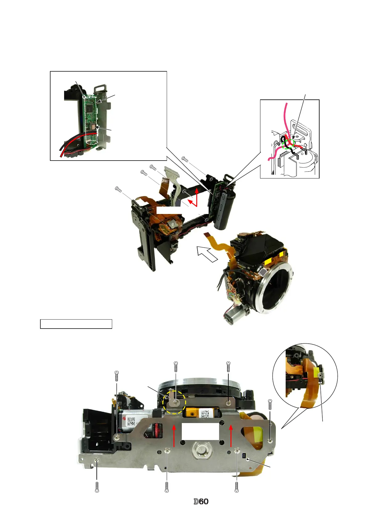
The wire that is connected
from the relay-PCB must not
mount on the other two wires.
#691
#691
#616×5
Bottom base plate unit
(#B66)
Direction for
positioning
#135
FPC must NOT
mount on this.
①
②
③
④
①
⑤
②
③
④
⑥⑦
Direction for positioning
・
Pass the wires of the relay-PCB through behind the main condenser, and assemble the front body into the rear
body.
・
Tighten four screws (#624) in the order from
①
to
④
.
3. Mounting of Front body on Rear body
SB-PCB
Main condenser
Do NOT let wires
mount on the coil.
Bottom base plate unit
・
Mount the bottom base plate unit (#B66) so that [#135] comes in front, and
tighten two screws (#691) and ve screws (#616) in the order from
①
to
⑦
.

 Loading...