32Service Manual – SC401, SCRUBTEC 344 04 - Control System - Battery
Wiring Diagram
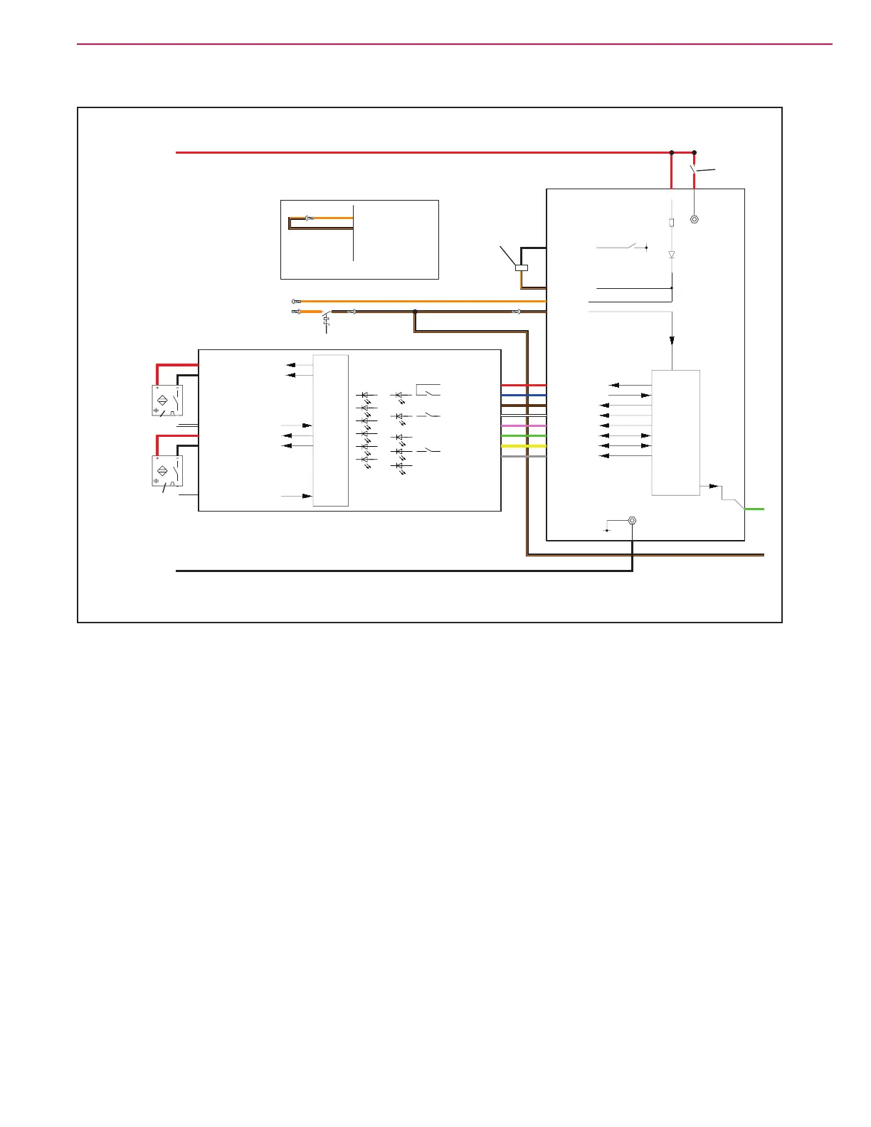
MAIN MACHINE
CONTROLLER (EB1)
USER INTERFACE
CONTROLLER (EB2)
RH OPERATOR’S
PRESENCE SENSOR (S1)
LH OPERATOR’S
PRESENCE SENSOR (S2)
MAIN MACHINE
CONTROLLER
RELAY (ES1)
MAIN MACHINE
CONTROLLER
RELAY (ES1)
IGNITION KEY (KEY)
RIGHT.25V
RIGHT.10V
LEFT.2 5V
LEFT.1 0V
RIGHT.3ENABLE
LEFT.3
Left op. pres. sensor supply +
Left op. pres. sensor supply -
Left op. pres. sensor input
Right op. pres. sensor supply +
Right op. pres. sensor supply -
Right op. pres. sensor input
ENABLE
KEY INPUT
BTN.1
J201.8
J201.7
J201.6
J201.5
J201.4
J201.3
J201.2
J201.1
Power button output
Power button input
Power supply +
Power supply -
SPI CS3
SPI MISO
SPI MOSI
SPI clock
KEY.2
KEY.1
Key input
Key output
B/R.2
B/R.3
Power relay +
Power relay -
24V
0V
PTC
FUSE
B/R.1 24V (LOGIC) Power supply + (permanent)
B+ 24V (POWER)
B-
0V
BTN.2 IGNITION
EXT.1 Power supply +
Power button input
Power button output
Power supply -
SPI CS3
SPI MISO
SPI MOSI
SPI clock
5V
EXT.2 0V
EXT.11 SPI CS3
EXT.3 SPI MISO
EXT.4 SPI MOSI
EXT.6 SPI CLOCK
uP
uP
MAIN MACHINE
CONTROLLER (EB1)
KEY.2
BASE MACHINE (WITHOUT BATTERY CHARGER AND KEY)
KEY.1
P1
P2
P3
LD7
LD8
LD9
LD10
LD11
LD6
LD5
LD4
LD3
LD2
LD1
D.2Drive system enable output
DRIVE ENABLE (5V)
Figure 3:
 Loading...


