76Service Manual – SC401, SCRUBTEC 344 05 - Control System - Cord
Operator’s Presence Sensors (S1, S2)
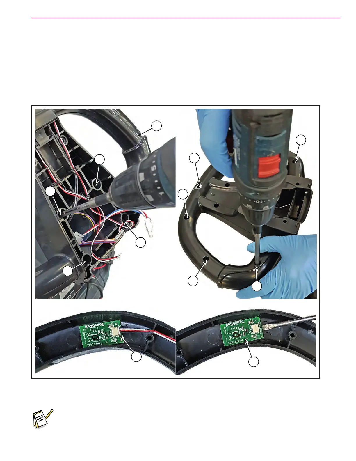
1. After removing the user interface controller cover and its connections, unscrew the 4 screws (G) then
remove the handlebar (H).
2. At the workbench, unscrew the 7 screws (I) the open the two handlebar parts front and back.
3. Disconnect the connection (J), with the screwdriver carefully remove the operator’s presence sensor (K)
detaching it from the support.
4. Clean the support area from the glue remained of the operator’s presence sensor removed.
Figure 18:
G
G
G
G
I
I
I
I
I
J
K
H
5. Assemble the components in the reverse order of dissasembly.
Note: The new operator’s presence sensor is provided with an self-adhesive seat for assembling.
 Loading...


