61Service Manual – SC401, SCRUBTEC 344 04 - Control System - Battery
User Interface Controller (EB2)
Measure and record the voltage at each of the Main machine controller pins. Always use battery negative as
your reference point for your black voltmeter lead.
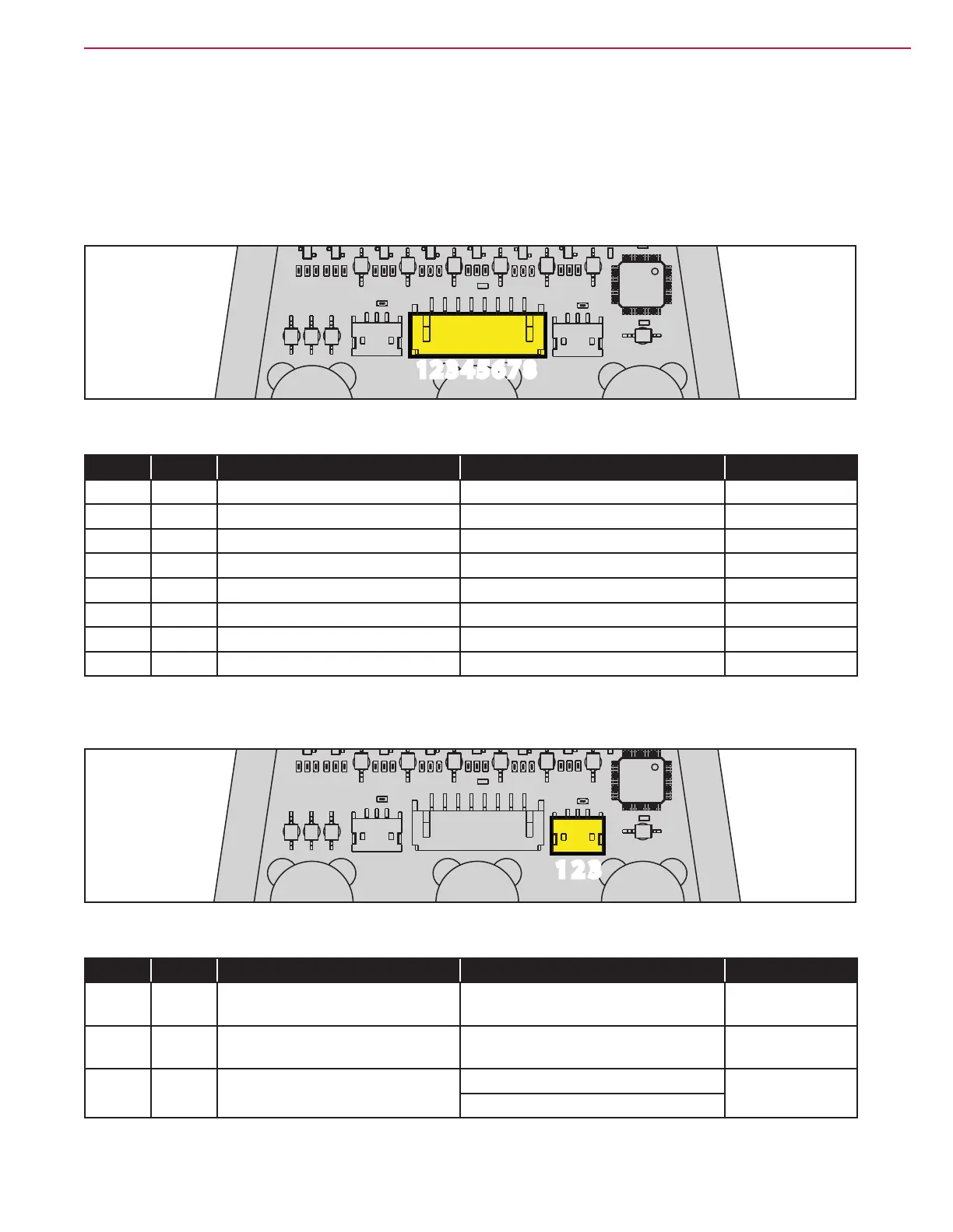
J201
1 2 3 4 5 6 7 81 2 3 4 5 6 7 8
Figure 51:
PIN Color Circuit Description Measured Comments
1 Grey SPI clock 0 - 5 V
2 Yellow SPI MOSI 0 - 5 V
3 Green SPI MISO 0 - 5 V
4 Pink SPI CS3 0 - 5 V
5 White Power supply - 0.00 V
6 Brown Power supply + 5.10 V (Machine ON)
7 Blue Power button output 23.85 V (While pressing Main button)
8 Red Power button input 23.85 V (Machine ON and OFF)
Left Operator’s Presence Sensor
1 2 31 2 3
Figure 52:
PIN Color Circuit Description Measured Comments
1 Red Left operator presence sensor
supply -
0.03 V Machine ON
2 Black Left operator presence sensor
supply +
5.10 V Machine ON
3 White Left operator presence sensor
input
4.26 V (No operator)
0.09 V (With operator)
 Loading...


