44Service Manual – SC401, SCRUBTEC 344 04 - Control System - Battery
User Interface Controller (EB2) and Operator’s Presence Sensors (S1, S2)
User Interface Controller (EB2)
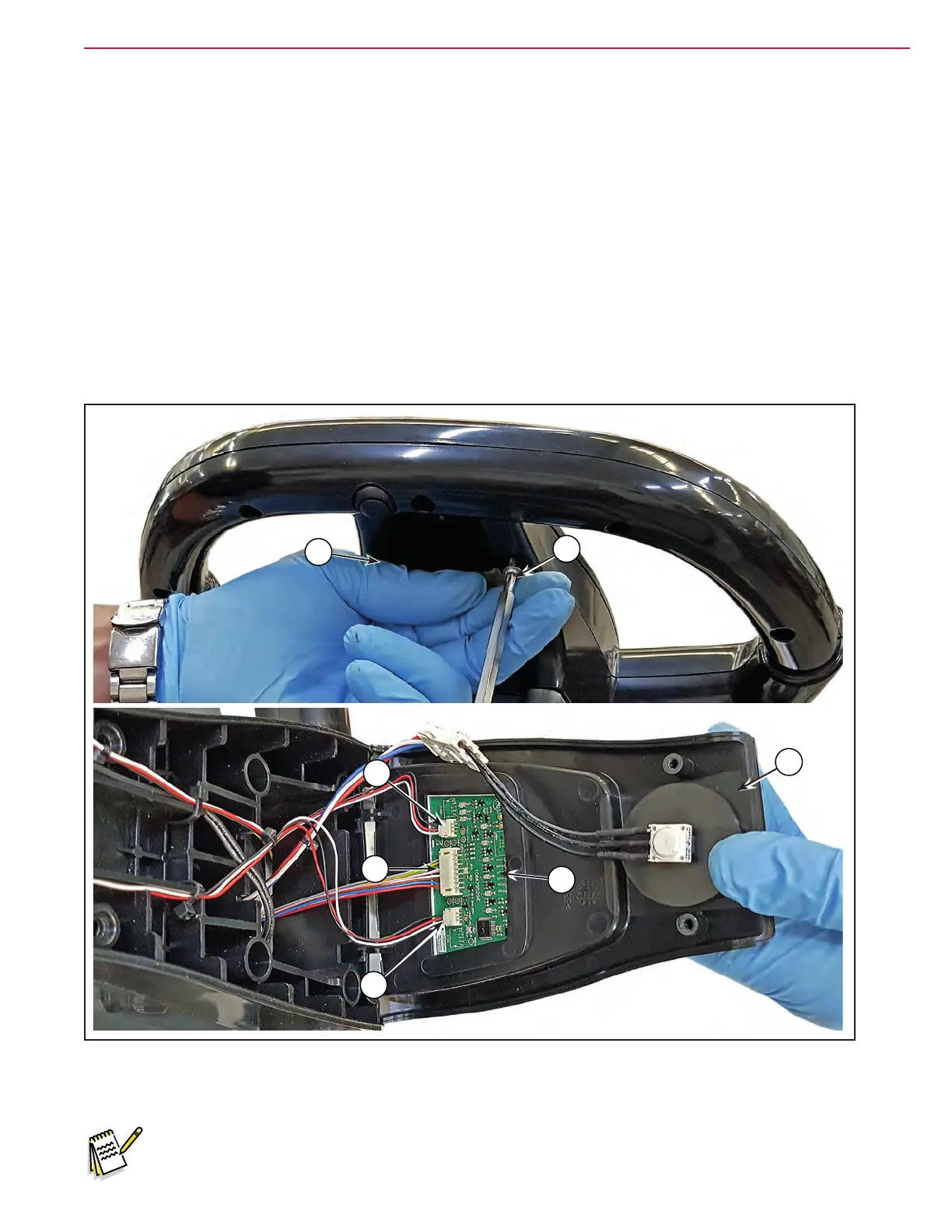
1. If equipped remove the ignition key, then disconnect the red battery connector.
2. Unscrew the 2 screws (A) and open the user interface controller cover (B).
3. Disconnect the following connections:
◦ (C) and (D), left and right Operator’s presence sensors connection.
◦ (E) User interface controller power supply connection (J201).
4. Carefully remove the User interface controller (F) detaching it from the cover (B).
5. Clean the cover area from the glue remained of the User interface controller removed.
Figure 22:
A
A
B
D
F
C
E
6. Assemble the components in the reverse order of disassembly.
Note: The new User interface controller is provided with an self-adhesive seat for assembling.
 Loading...


