4-12
Security 15088:J 10/22/99
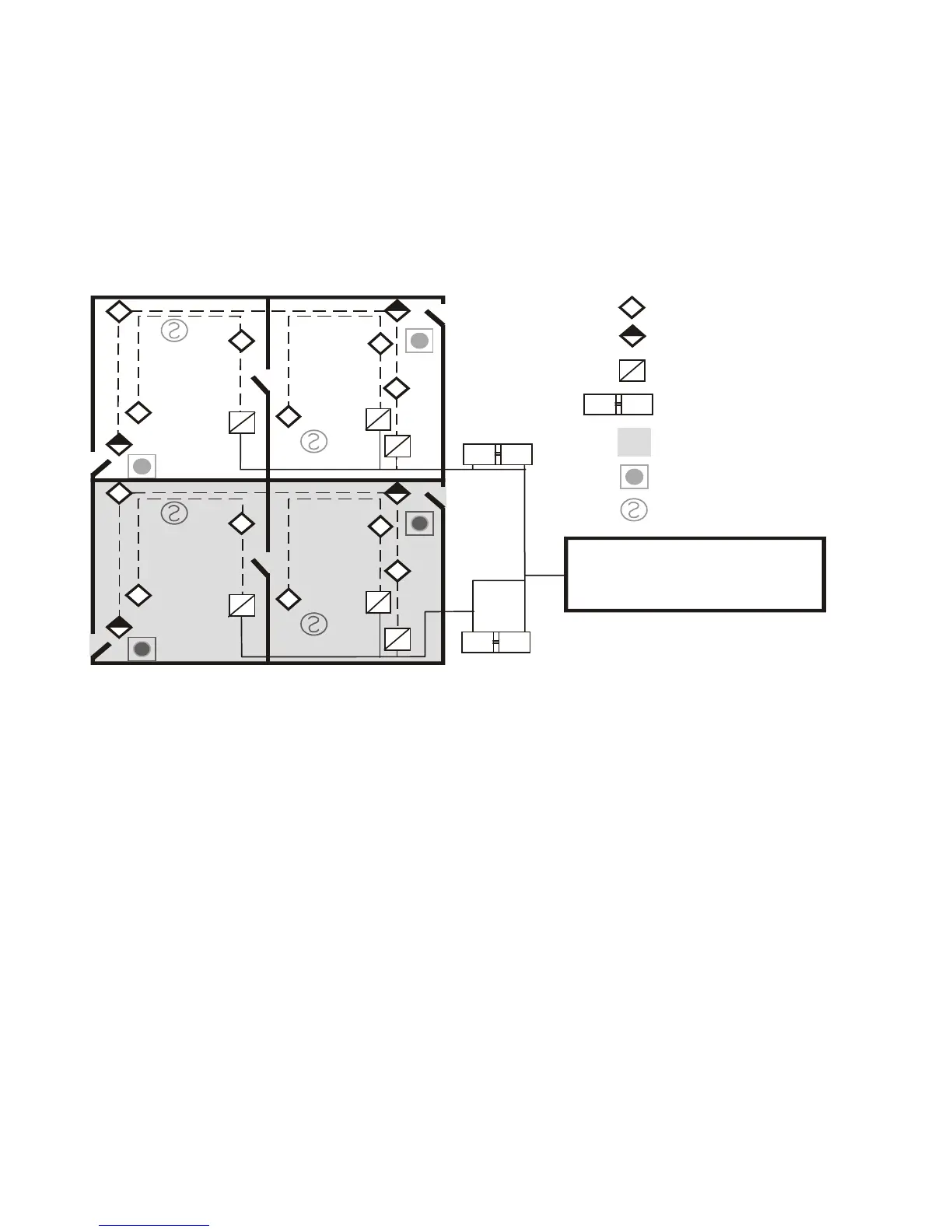
Programming Key for Figure 1.3-5
Programming relating to Figure 1.3-5 is essentially the same as Figure 1.3-4. The only difference in program-
ming is that (Za) Control By Event value for Tenant A and (Zb) Control By Event value for Tenant B must be used,
where Za is a zone number and Zb is a different zone number.
The following system requirements are illustrated in Figure 1.3-5. See Table 1.1-1 in the introduction to this
section for monitor and control module options.
• One AM2020/AFP1010 Control Panel
• Multiple Security Supervisory Circuits Reporting to Central Station as a Single Area
• Multiple Protected Premises
• The minimum security equipment required is as follows:
— Multiple Monitor Modules per protected area
— one group interface per grouped area
— security devices
Figure 1.3-5 Multiple Tenant Consolidation Security System
The following system requirements are illustrated in Figure 1.3-6. See Table 1.1-1 in the introduction to this
section for monitor and control module options.
• One AM2020/AFP1010 Control Panel
• One Security Supervisory Protected Area
• One Protected Premises
• System Arm/Disarm Capability with Central Station Ringback Signal
• The minimum security equipment required is as follows:
— Monitor Module for Protected Area
— Contact Switch for Entry/Exit Door
— RKS-S Remote Keyswitch
— Monitor Modules
— One Group Interface
— ACM-16AT or ACM-32A Remote Annunciator for Entry/Exit Door
— Security Devices
— One Group Interface
Key
Motion Detector
Contact Switch
Pull Station
Smoke Detector
MM Security Area Monitor
Group Interface
*
* Group Interface must be physically
located in either the protected
premises or the Central Station
MM C M
AM2020/AFP1010
Central Station
Area5.cdr
Shaded Area Indicates
Second Tenant
MM C M
Signaling
Line
Circuit
TENANT A
AREA 1
(Perimeter
and
Interior)
*
MM C M
TENANT B
AREA 1
(Perimeter
and
Interior)
www.PDF-Zoo.com
 Loading...


