1-17
Installation 15088: J 10/22/99
NOTE
For installation of system boards in the first level of the
ICA-4L, omit Steps 2 and 3.
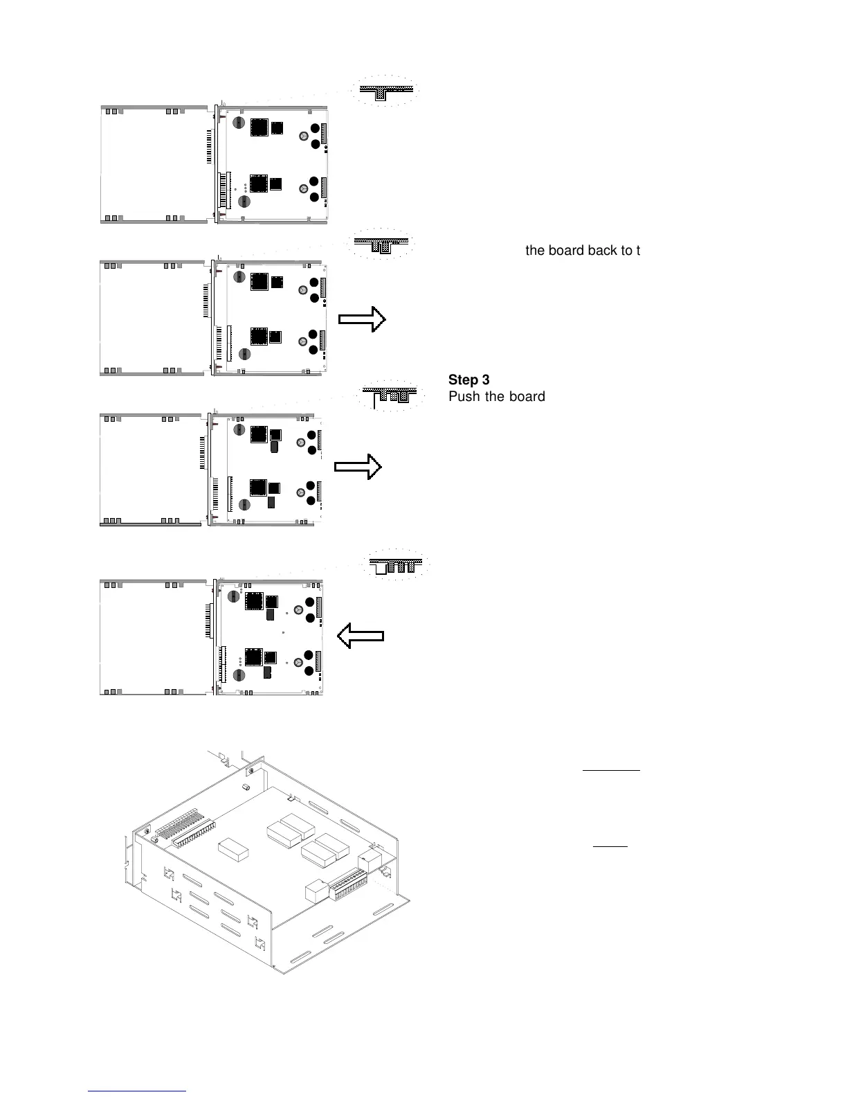
Figure 2.3-8 Mount System Boards to the ICA-4L Chassis
Step 1
Place the board in front of the Interconnect Chassis
Assemblies (ICA-4L) in the position where it will be
installed. Tilt the board into the ICA-4L and align the
square slots on the board with the first set of four tabs
on the ICA-4L as illustrated.
○
○○○○○
○○○
○
○
○○
○
○○
○
○○○
Step 3
Push the board back again to the second level and
then slide it away from the ICA-4L until it is directly
over the third set of four tabs, now located immediately
behind the printed circuit board.
Step 4
Now push the board back so that it is resting on the
four tabs behind the board. Slide the board inward
toward the center of the ICA-4L and carefully engage
the female connector on the board with the male
connector on the ICA-4L. When the board is correctly
seated, it will be stopped by a mechanical tab. Some
force is required. Before applying force, carefully
check alignment of all pins. When finished, the board
should be seated in a channel consisting of four
retaining tabs in front of the printed circuit board and
four retaining tabs behind the printed circuit board.
○○○○○○○○○○
○○○○○○○○○○
Step 2
Carefully push the board back to the first level and then
slide it away from the ICA-4L, until it is directly over the
second set of four tabs, now located immediately behind
the printed circuit board.
CAUTION
Remove Serial Interface Boards (SIBs) carefully, as the
metal tabs on the ICA-4L may shear off some of the SIB
components.
www.PDF-Zoo.com
 Loading...


