44473001TH Rev.1
50 /
Oki Data CONFIDENTIAL
2. DESCRIPTION OF OPERATION
2.3 Image Scanning process
2.3.1 Structure and process of RADF
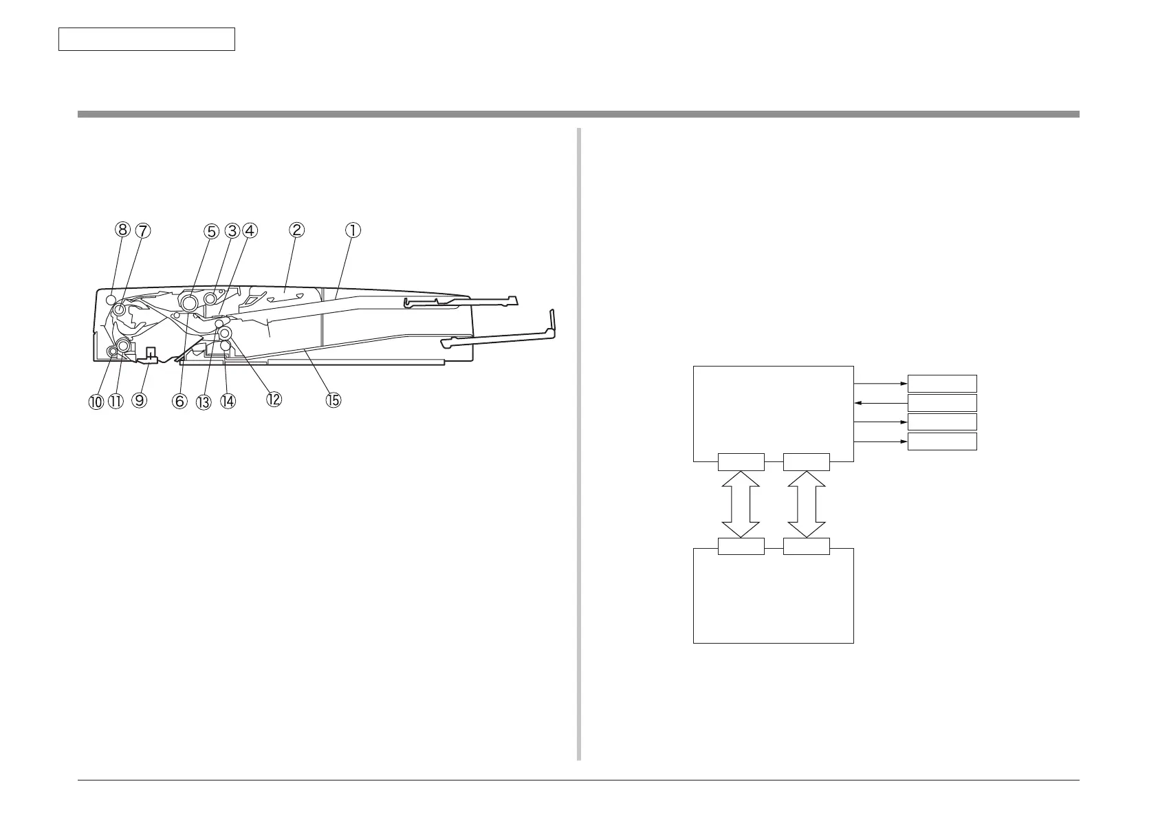
2.3.1.1 Cross-section view
1 Paper tray 9 Regist roller
2 Paper guide 10 Pressure roller
3 Pick-up roller 11 Paper weight
4 Friction pad 12 Exit roller
5 Feed roller 13 Upper pinch roller
6 Separation pad 14 Lower pinch roller
7 Transfer roller 15 Paper stcker
8 Pinch roller
2.3.1.2 Electrical configuration
Electrical circuit configuration
Electrical control of the MFP is executed by the main controller circuit PCB.
The ASIC of the main controller circuit PCB interpret the input signals that are supplied from
sensors and the signals that are supplied from the externally connected equipment.
The ASIC output thesignals that drive the DC load devices such as motor, solenoid and
clutch in accordance with the specified timings.
The ADF relay circuit PCB do not contain the memory area.
The data such as service mode data is stored in the main controller circuit PCB.
Motor
MOTIF
ADF relay PCB
Main controller PCB
+24V +3.3V
ADFM
SNSIF
ADFS
Sensor
Solenoid
Clutch
 Loading...