44473001TH Rev.1
92 /
Oki Data CONFIDENTIAL
4.REPLACEMENT OF PARTS
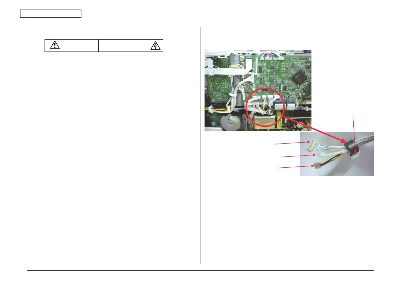
Exit connector
Fuser connector
Rear fan connector
Exit cable wound one
turn around core
Note! The LED head cables
s
hould be attached, the
end of the Film-FG being
placed inside the Plate-
side-R so as that they
touch no sheet metal
edges of the Plate-side-R.
4.2.5 CU/PU PCB and low-voltage power supply
Electric shock hazard
When replacing the low-voltage power supply, electric shock may occur. Wear insulated
gloves, or be careful not to touch the conductors or terminals of the power supply directly.
After the AC cord is unplugged, the capacitor may take about one minute to discharge
completely or, due to PCB breakdown, could not discharge. Use caution about electric shock.
(1) Remove the right side cover. (See 4.2.4)
(2) Remove the four (silver-colored) screws
①
(2
) Remove the five (silver-colored) screws
②
and unlatch and remove the plate shield
assembly
③
.
(3
) Remove all the CU/PU board cables.
(4) Remove the three (silver-colored) screws
④
to detach the PU/CU PCB
⑤
.
(5
) Remove all the low-voltage power supply cables.
(6) Remove the two (silver-colored) screws
⑥
to detach the low-voltage power supply
⑦
.
 Loading...