78
Specifications Section 3-1
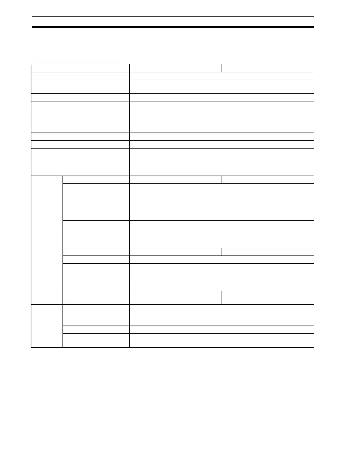
3-1 Specifications
3-1-1 Specifications
Note 1. Do not apply a voltage higher than 600 V to the terminal block when per-
forming withstand voltage test on this Unit. Otherwise, internal elements
may deteriorate.
2. Refer to Dimensions on page 359 for details on the Unit’s dimensions.
Item CJ1W-AD041-V1 CJ1W-AD081-V1
Unit type CJ-series Special I/O Unit
Isolation (See note 1.) Between I/O and PLC signals: Photocoupler
(No isolation between individual I/O signals.)
External terminals 18-point detachable terminal block (M3 screws)
Affect on CPU Unit cycle time 0.2 ms
Power consumption 420 mA max. at 5 VDC
Dimensions (mm) (See note 2.) 31 x 90 x 65 (W x H x D)
Weight 140 g max.
General specifications Conforms to general specifications for SYSMAC CJ Series.
Mounting position CJ-series CPU Rack or CJ-series Expansion Rack
Maximum number of Units (See note 3.) Units per Rack (CPU Rack or Expansion Rack): 4 to10 Units max. (See note
3.)
Data exchange with CPU Units
(See note 4.)
Special I/O Unit Area in CIO Area (CIO 2000 to CIO 2959): 10 words per Unit
Special I/O Unit Area in DM Area (D20000 to D29599): 100 words per Unit
Inputs
specifica-
tions
Number of analog inputs 4 8
Input signal range
(See note 5.)
1 to 5 V
0 to 5 V
0 to 10 V
–10 to 10 V
4 to 20 mA
(See note 6.)
Maximum rated input (for 1
point) (See note 7.)
Voltage Input: ±15 V
Current Input: ±30 mA
Input impedance Voltage Input: 1 MΩ min.
Current Input: 250 Ω (rated value)
Resolution (See note 8.) 4,000/8,000 4,000/8,000
Converted output data 16-bit binary data
Accuracy
(See note 9.)
23±2°C Voltage Input: ±0.2% of full scale
Current Input: ±0.4% of full scale
0°C to 55°C Voltage Input:±0.4% of full scale
Current Input: ±0.6% of full scale
A/D conversion time
(See note 10.)
1 ms/250 µs
(See note 8.)
1 ms/250 µs
(See note 8.)
Inputs func-
tions
Mean value processing Stores the last “n” data conversions in the buffer, and stores the mean value of
the conversion values.
Buffer number: n = 2, 4, 8, 16, 32, 64
Peak value holding Stores the maximum conversion value while the Peak Value Hold Bit is ON.
Input disconnection detec-
tion
Detects the disconnection and turns ON the Disconnection Detection Flag.
 Loading...


