187
Wiring Section 5-4
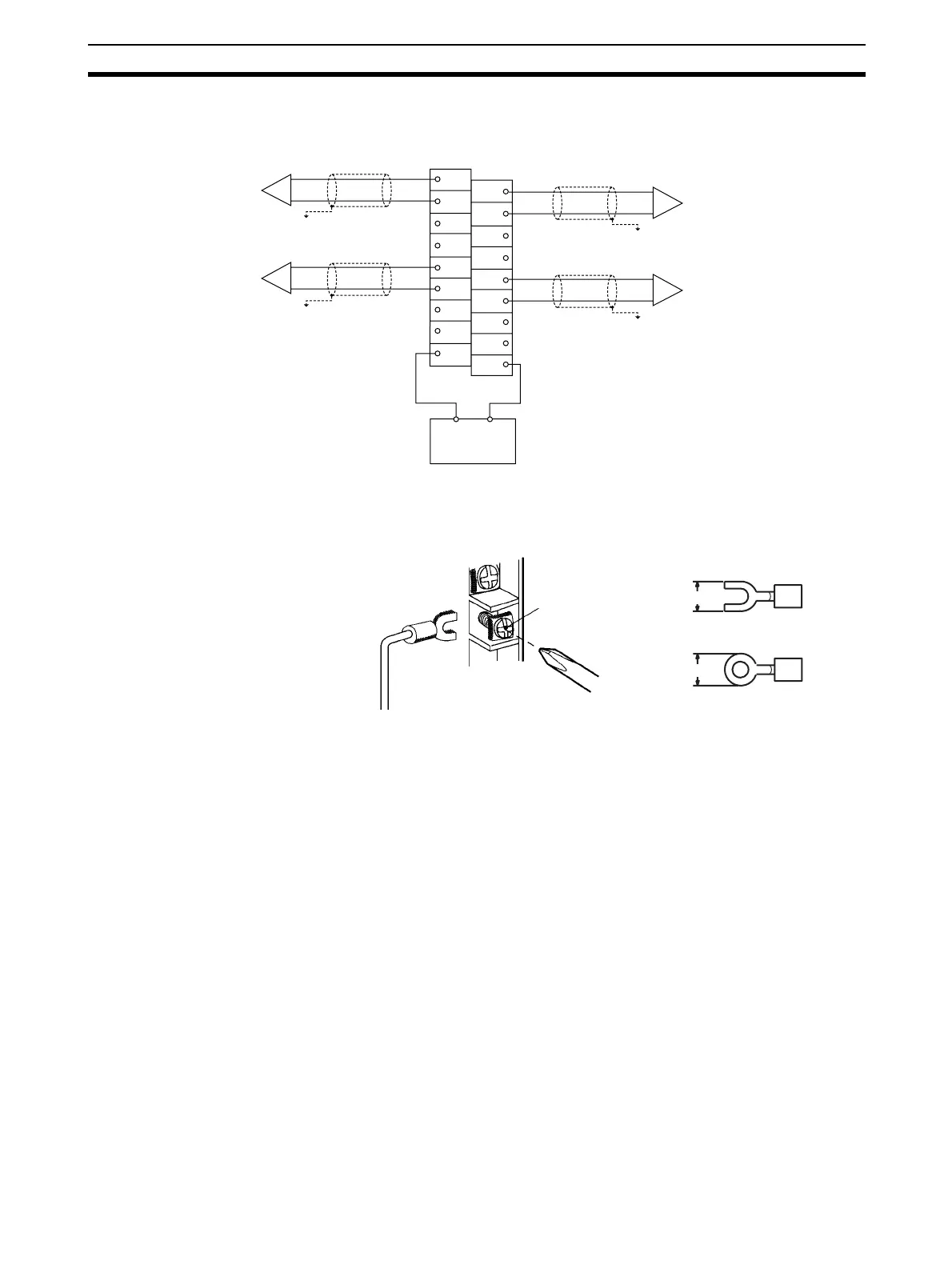
5-4-3 Output Wiring Example
Note Crimp-type terminals must be used for terminal connections, and the screws
must be tightened securely. Use M3 screws and tighten them to a torque of
0.5 N·m.
To minimize output wiring noise, ground the output signal line to the input
device.
5-4-4 Output Wiring Considerations
When wiring outputs, apply the following points to avoid noise interference
and optimize Analog Output Unit performance.
• Use two-core shielded twisted-pair cables for output connections.
• Route output cables separately from the AC cable, and do not run the
Unit’s cables near a main circuit cable or a high voltage cable. Do not
insert output cables into the same duct.
• If there is noise interference from power lines (if, for example, the power
supply is shared with electrical welding devices or electrical discharge
machines, or if there is a high-frequency generation source nearby) install
a noise filter at the power supply input area.
• Use a separate power supply for the external power supply from the one
used for Basic I/O Units. If the same power supply is used, noise may
cause Units to malfunction.
Output 2
(voltage output)
Output 4
(current output)
Output 1
(voltage output)
Output 3
(current output)
0 V
24 VDC
External
power supply
+
−
−
+
+
−
−
+
B1
B2
B3
B4
B5
B6
B7
B8
B9
A1
A2
A3
A4
A5
A6
A7
A8
A9
CJ1W-DA041
6.0 mm max.
6.0 mm max.
M3 screw
Fork type
Round type
 Loading...


